
Data Sheet


-6-
both machines you will need to install the motor and speed
control. Some of these parts are assembled and tested for t
at the factory prior to shipping. They are then disassembled
and packaged, so everything should go together easily when
you reassemble it. The motors are “run in” for approximately
one hour to assure proper function and seating of the brushes.
Before you call us and say a part is missing, please look
carefully through the packaging. Some parts are in bags taped
to the bottom of cardboard aps or spacers, and you may not
notice them when you open the box and remove the major
components.
LATHE—Mounting the Crosslide
Installation of the crosslide requires no tools. It is located under
a ap of cardboard that retains the lathe base in the shipping
box. First, make sure the bottom of the crosslide has a light
coat of grease on all the sliding surfaces. This will have been
applied at the factory, just make sure it has not been wiped
o and that it is evenly distributed.
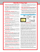
Next, see that the gib is in the proper position on the saddle.
(See Figure 4.) It is taped into position for shipping. Remove
the tape holding it in place. If the gib has come o, reposition
it on the gib lock as shown.
From the front of the lathe, engage the crosslide dovetail with
the gib and matching dovetail on the saddle. Slide it onto the
saddle about 1/4" (6-7 mm) until it stops. (See Figure 5.)
Look underneath and align the slide screw with the threads
on the brass slide screw insert on the side of the saddle. (See
Figure 6.) Turn the crosslide handwheel clockwise to engage
the threads. Continue to crank the handwheel clockwise until
the crosslide is in the desired position on the saddle.
All MILLS—X-Axis Handwheel Installation
Mills with adjustable “zero” handwheels come with the X-axis
handwheel removed to prevent damage to the leadscrew during
shipping. Reinstalling the handwheel is a simple process:
1. Loosen the X-axis table lock (the barrel-shaped lock on
the saddle that is tightened against the side of the mill
table with a socket head cap screw). From the end of the
mill table where the X-axis leadscrew protrudes, push
on the end of the mill table to make sure it seats tightly
against the leadscrew.
2. Examine the red collar on the handwheel to see that the
small hole is aligned with the head of the set screw. If it
is not, loosen the black locking nut on the handwheel and
rotate the collar until you can see the head of the set screw.
FIGURE 5—Installing
the crosslide table onto
the saddle
FIGURE 6—Aligning the slide screw with the brass slide screw
insert
3. The handwheel was installed at the factory and then
removed for shipping. You should be able to see a mark
on the leadscrew where the set screw was previously
tightened. When reinstalling the handwheel, try to have
the set screw pick up this same position on the leadscrew.
4. Slide the handwheel onto the end of the leadscrew shaft
and push until the handwheel is fully seated and the thrust
collar is clamped tightly between the handwheel and the
leadscrew collar. A 3/32" hex wrench is included with
your machine to tighten the handwheel set screw.
Digital Readout Handwheels
If you ordered your mill equipped with a digital readout, the
X-axis handwheel will again be removed to prevent damage
during shipping. The proper thrust collar has been factory
installed. If a 1/4" shim washer is required, it will be included
in this package. Place it on the leadscrew shaft before installing
the handwheel. Follow the installation instructions included
with the P/N 8100 digital readout to install the encoder housing
and handwheel unit.
5000-Series Mills—Mounting the Column
The mill is shipped attached to a piece of
plywood to keep it from moving in the box.
Before you begin, remove the screws holding
the mill base to the plywood. It was installed
strictly for packing purposes and will need to
be removed so that the column can be installed.
The Z-axis column is mounted to the base with
two 1-3/4" long, 1/4-20 socket head screws.
These screws and the hex key tool you will
need to tighten them are packaged in the bag
with the motor mounting bracket and
drive belt. It is much easier to
mount the column to the base
before you mount the motor and
speed control to the saddle.
Set the column on the base
aligned with the mounting holes
and hold it in position while you
insert the rst screw up from the
SLIDE SCREW INSERT
FIGURE 7—Mounting the
5000-series mill Z-axis
column
Video instructions for assembling Sherline lathes and
mills can be viewed at sherline.com/sherline-videos/.
GIB
GIB LOCK
SADDLE
SLIDE SCREW INSERT and
ANTI-BACKLASH NUT
FIGURE 4—Lathe bed, saddle, and gib
ANTI-BACKLASH
LOCK