
Data Sheet


-32-
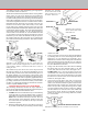
You can also use
miniature series
end mills having
3/16" or 1/4" shank
sizes which should
be held in collets
or end mill holders
sized for those tools.
Many “Dremel
®
”
type cutting tools
come with a 1/8"
shank. End mills held
in collets must be
single-ended, while end mill holders are capable of holding
single- or double-ended end mills. We recommend using 2-ute,
high-speed steel (HSS) end mills for aluminum because the
utes are less prone to clog with chips. Use 4-ute cutters for
cutting steels with lower RPM. The solid carbide tools are not
suggested since they are very expensive and the cutting edges
will chip unless used with heavy-duty production equipment.
As a convenience to our customers, Sherline keeps in inventory
many of the popular sizes of end mills that are appropriate for
use on our machines. See our “Cutting Tools Price List” for
selection. End mills may also be purchased on-line or from
your local industrial machine shop supply outlet. Do a search
for or see the yellow pages under “Machine Shop Supplies.”
Because small diameter cutters (less than 1/8") are quite fragile,
the largest diameter cutter possible for the job requirements
FIGURE 64— 4- and 2-ute double-
ended end mill sets.
Cutting Speeds for Milling
Speed Adjustment Chart
SPINDLE RPM = 3.82 x S.F.M.
D
S.F.M. = The rated Surface Feet per Minute for milling. For
drilling, use 60% of the rated surface feet.
RPM = The rated spindle speed in Revolutions Per Minute
D = The Diameter of work in inches
FIGURE 63—Formula for adjusting spindle speed for cutting
a given diameter.
NOTE: To estimate RPM, remember that the speed range of
your vertical mill is from 0 to 2800 RPM. (The lowest usable
speed is about 70 RPM, so we use that in our specications.
To obtain much more torque at the lower speed ranges, the
drive belt can be switched to the smaller diameter positions
on the spindle and drive pulleys.) Therefore, in the normal
belt position, half speed is approximately 1450 RPM and so
on. You can estimate these speeds by a combination of the
setting on the speed control knob and the sound of the motor
itself. When using the optional digital readout (P/N 8100),
the exact RPM is displayed constantly on the LCD screen.
End Mills
End mills are the standard cutting tools used on a vertical mill.
We recommend 3/8" shank end mills held in the 3/8" end mill
holder (P/N 3079). One of the benets of 3/8" end mills is
that they are available in a large range of sizes. The end mill
is held with a set screw on its at surface, and it can be easily
changed. They are also lower in price than miniature cutters
because of their popularity.
END MILLS (Slot and side milling)
MATERIAL CUT SPEED (S.F.M.) 1/8" DIA. 1/4" DIA. 3/8" DIA.
Stainless Steel, 303 40 1200 RPM 600 RPM 400 RPM
Stainless Steel, 304 36 1100 500 350
Stainless Steel, 316 30 900 450 300
Steel, 12L14 67 2000 1000 650
Steel, 1018 34 1000 500 350
Steel, 4130 27 800 400 250
Gray Cast Iron 34 1000 500 350
Aluminum, 7075 300 2800 2500 2000
Aluminum, 6061 280 2800 2500 2000
Aluminum, 2024 200 2800 2500 2000
Aluminum, Cast 134 2800 2000 1300
Brass 400 2800 2800 2800
DRILLS
MATERIAL CUT SPEED (S.F.M.) 1/16" DIA. 1/4" DIA.
Carbon Steel 36 2000 RPM 550 RPM
Cast Iron, Soft 30 1800 450
Stainless Steel 24 1400 360
Copper 72 2000 1100
Aluminum, Bar 240 2000 2000
Aluminum, Cast 120 2000 2000
should be employed. Be certain that the RPM is appropriate
before attempting to remove any metal. An end mill can be
instantly damaged if a cut is attempted at excessive RPM. Like
all cutting tools, end mills will have a short life span when
used for machining steel or other exotic materials. Save new
cutters for nish work. Because of excessive cutter deection
(bending), do not use small diameter end mills with long utes
unless absolutely necessary.
Resharpening End Mills
End mills can be resharpened by your local tool and cutter
grinding shop. End mills lose their cutting edge clearance
after a couple of sharpenings and should no longer be reused.
Using the Mill Column Saddle Lock
The saddle locking lever is located on the back side of the mill
column just above the saddle nut. This lever tightens against
the saddle nut on the column leadscrew to keep it from moving
during milling operations.
With the lever released, adjust the Z-axis handwheel to the
desired setting. Rotate the lever counter-clockwise to lock
the saddle. This will eliminate any backlash in the leadscrew.
Friction on the gib can still cause a little backlash to be present
between the handwheel and the leadscrew thrust. To eliminate
this, push down on the saddle to make sure the handwheel
is fully seated against the thrust. Double check your height
adjustment. Now, when milling, the saddle cannot move any
further down.
To release the saddle, rotate the lever clockwise. A spring-
loaded ball in the saddle ts in a detent on the lever to keep
it from locking accidentally when the Z-axis is adjusted. (See
Figure 66.)
An adjustable saddle lock is available that allows adjustment
of backlash on the Z-axis. This is particularly useful in CNC
applications but can be used on manual machines as well. It is
standard on new CNC machines and available as an upgrade
for manual machines as P/N 4017Z/4117Z.
FIGURE 65—Drill and milling cutter speed chart.