
Data Sheet


-11-
board using four 10-32 screws with washers and nuts. Lengths
should be 1-1/2" for short bed lathes and 1-7/8" for long bed
lathes. Rubber feet should be attached at each corner on the
bottom of the mounting boards. They are also readily available
in hardware stores. This arrangement gives the machines a
stable platform for operation yet still allows for easy storage.
The rubber feet help minimize the noise and vibration from
the motor. Mounting the tool directly to the workbench can
cause vibration of the bench itself, which acts as a “speaker”
and actually amplies the motor noise. Bench mounting also
eliminates one of the best features of Sherline machines...the
ability to be easily put away for storage.
The mill may be mounted in a similar manner on a 10" x 12"
to 12" x 20" nished shelf board with rubber feet using 10-32
x 1" screws to attach the mill to the board. You may want to
drill clearance holes through the mill base board to access the
column screws so the column can later be removed from the
mill without removing the mill base from the mounting board.
REMEMBER: Do not lift your machine by the motor!
Carry the machine by lifting under the base or by the mounting
board. The cast motor bracket was not designed for lifting.
To keep your Sherline tools clean, soft plastic dust covers are
available. The lathe cover is P/N 4150 for the Model 4000/4100
and 4500/4530 short bed lathes and P/N 4151 for the Model
4400/4410 long bed lathe. A mill dust cover is available as
P/N 5150 for 5000-series mills and P/N 5151 for 2000-series
8-direction mills.
Converting Machines from Inch to Metric and Vice Versa
All Sherline tools and accessories are manufactured in your
choice of inch or metric calibrations. Converting a lathe or
mill from one measurement system to the other is possible, but
it takes more than changing the handwheels. The leadscrews,
nuts and inserts must also be changed. A look at the exploded
views of the machines on pages 45 through 52 will show which
parts need to be purchased. (Look for parts that have both a
metric and inch version in the parts listing.) Conversion kits
with all the necessary parts are available. If you are a good
mechanic, you can do the conversion yourself, or you can
return your machine to the factory for conversion.
ADJUSTMENTS
Two-Speed Pulley
The normal pulley position, which is placing the belt on the
larger motor pulley and smaller headstock pulley, will suce
for most of your machining work. Moving the belt to the other
position (smaller motor pulley, larger headstock pulley) will
provide additional torque at lower RPM. It is particularly
useful when turning larger diameter parts with the optional
riser block in place. To change the pulley position, remove the
speed control hold-down screw and pivot the speed control
housing up out of the way. Remove the mounting plate from
its position on the rails of the two halves of the belt guard
housing. Loosen the two nuts that hold the motor to the motor
mounting bracket and take the tension o the belt. With your
nger, push the belt o the larger diameter groove of the
pulley and into the smaller one. (Depending on which way
you are changing it, this could be either the motor or spindle
pulley.) Then move the belt to the larger diameter groove on
the other pulley, and rotate the headstock by hand to get it to
seat. Push the motor outward on the motor mounting bracket
to put the proper tension on the belt, and retighten the two
motor mounting screws. Now you can replace the mounting
plate, pivot the speed control back down, and refasten it.
Moving the belt back to the other position is simply a reverse
of the above procedure.
Spindle Preload Adjustment
If any end play develops in the main spindle, it can be easily
eliminated by re-adjusting the preload nut. (See part number
40160 in the exploded view.) When the headstock is assembled
at the factory, the preload nut is adjusted to .0002" (.005 mm)
of end play. This is controlled by the outer races of the bearing
being held apart by the headstock case and the inner races being
pulled together by the preload nut. This setting was determined
through experience, and, like everything in engineering, it is
a compromise. If the machine is only to be run at high-speed,
this setting may be too “tight.” The headstock will run fairly
warm to the touch normally, but extended periods of high
speed operation may bring about excessive temperature. The
headstock should not become too hot to touch. If this is your
case, the preload tension may need to be reduced slightly.
To change the adjustment, remove the spindle pulley, loosen
the set screw in the preload nut and back the preload nut o
4° of rotation (counter-clockwise). The bearings are lightly
pressed into the case, so the inner race will not move without a
sharp tap with a plastic mallet to the end of the spindle where
the pulley is attached.
If you nd your bearings are set too loose, you may want to
take up on the end play. You can check them with an indicator
or by spinning the spindle without the motor belt engaged.
If the spindle spins freely with a chuck or faceplate on it,
the spindle is too loose for normal work. Adjust the preload
nut until it turns only about one and a half revolutions when
spun by hand.
CAUTION! Check the Tightness of all Bolts—Vibration in shipping can cause some bolts or screws to loosen up. Before
using your new machine, check the tightness of all fasteners. It is also a good idea to check tightness periodically when
using the machine, as vibration from operation may cause some fasteners to loosen up.
FIGURE 19—Machines mounted to a base board for stability.
RUBBER FEET
A B
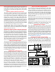
FIGURE 20—The two pulley positions. Position A is the
conventional setting, position B oers more torque at low
RPM when turning large diameter parts.
Approximate RPM range: A=70-2800, B=70-1280
NORMAL BELT POSITION
HIGH TORQUE, LOW RPM POSITION