
Sherline 4400 Lathes - Assembly and Instruction Guide
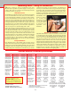
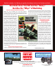
Table Of Contents
- Safety Rules for Power Tools
- An Introduction to the World of Miniature Machining
- Machine Terminology
- The Customer's Responsibility
- Learning More About Machining
- Visit the Sherline Website for the Latest Updates
- Lubrication
- Initial Assembly of a New Machine
- LATHE—Mounting the Crosslide
- All MILLS—X-Axis Handwheel Installation
- Digital Readout Handwheels
- 5000-Series Mills—Mounting the Column
- 2000- and 5800-Series Mills—Assembling and Mounting the Multi-Direction Column
- Mounting the Motor and Speed Control Unit to the Headstock
- Operation of the Motor and Electronic Speed Control
- What to Do if the Motor Suddenly Shuts Down
- Replacing Brushes on a DC Motor
- Mounting the Lathe or Mill to a Board for Stability
- Converting Machines from Inch to Metric and Vice Versa
- ADJUSTMENTS
- Two-Speed Pulley
- Spindle Preload Adjustment
- Gib Adjustment (Lathe and Mill)
- Backlash Adjustment (Lathe and Mill)
- Handwheel Adjustment (Lathe and Mill)
- Saddle Nut Adjustment (Lathe and Mill)
- Adjustment and Use of the Tailstock Gib
- Aligning the Headstock and Tailstock on the Lathe
- Squaring up Your Mill
- Use of Cutting Oils and Lubricants
- General Machining Terms
- Lathe Operating Instructions
- Digital Readouts, P/N 8200
- Live Center, P/N 1197
- Steady Rest, P/N 1074
- Thread Cutting Attachment, P/N 3100
- 3-Jaw, 4-Jaw and Drill Chucks
- Accessories for Your Lathe
- Guide to Approximate Turning Speeds
- Inserted Tip Carbide Tools
- Using the Cutoff or Parting Tool
- Tool Shapes and Grinding Your Own Cutting Tools
- Taper Turning
- Faceplate Turning
- Reaming
- Headstock Drilling
- Tailstock Drilling
- Center Drilling
- Removing Tools from the Morse Taper Spindles
- Turning Between Centers
- Holding the Workpiece
- Inducing Chatter and Learning How to Overcome It
- 3-Jaw Chuck Operation and Maintenance
- Vertical Milling Machine Operation
- Industrial Applications for Sherline Components
- Longer Tables and Taller Milling Columns Available
- Several Reasons to Consider CNC
- Learning About CNC
- CNC and CNC-Ready Sherline Lathes and Milling Machines
- CNC Rotary Indexer (P/N 8700)
- 4" Rotary Table (P/N 3700)
- Tilting Angle Table (P/N 3750)
- Mill Vise Set (P/N 3551)
- Drill Chucks (P/N 3072) and Center Drills
- Fly Cutters (P/N 3052 and P/N 7620)
- Boring Head (P/N 3054/3049)
- Mill Collet Set
- Drill Chuck Holder (P/N 3074)
- 3/8" End Mill Holder (P/N 3079)
- Accessories for Your Milling Machine
- Using the Mill Column Saddle Lock
- End Mills
- Cutting Speeds for Milling
- Determining the Depth of Cut
- Locating the Edge of a Part in Relation to the Spindle
- Using a Dial Indicator
- Standard Milling Versus Climb Milling
- Types of Milling Cutters
- Three Types of Work
- Purchasing Materials in Small Quantities
- Things to Consider Before You Start Cutting
- Locking the Axes
- Securing the Workpiece
- Helpful Tips for Milling
- General Description
- DRO Machine Operations
- Installing Stepper Motors
- Lead Wire Connection and Color Code
- Sherline Stepper Motor Specifications—Nmb Motors
- Using Handwheels on the Stepper Motors
- Stepper Motor Installation Instructions
- Sherline CNC Motor-Mounting Instructions
- Sherline Machine Technical Specifications

-53-
Sherline Machine Technical Specifications
LATHES 4000 (4100) 4400 (4410)
Swing over bed 3.50" (90 mm) 3.50" (90 mm)
Swing over carriage 1.75" (45 mm) 1.75" (45 mm)
Distance between centers 8.00" (200 mm) 17.00" (430 mm)
Hole through spindle .405" (10 mm) .405" (10 mm)
Spindle nose ext. thread 3/4-16 T.P.I. 3/4-16 T.P.I.
Spindle nose int. taper #1 Morse #1 Morse
Spindle runout of Morse taper .0005" or less .0005” or less
Travel of crosslide 3.25" (83 mm) 3.25" (83 mm)
Tailstock spindle taper #0 Morse #0 Morse
Protractor graduations 0° to 45° by 5° 0° to 45° by 5°
Handwheel graduations .001" (.01 mm) .001" (.01 mm)
Leadscrew Pitch .050"/rev (1 mm/rev) .050"/rev (1 mm/rev)
Electronically controlled
spindle speed range 70 to 2800 RPM 70 to 2800 RPM
Length overall** 23" (584 mm) 32.5" (826 mm)
Width overall** 10.25" (260 mm) 10.55" (267 mm)
Height overall** 8" (203 mm) 8.5" (216 mm)
Shipping weight 24 lb. (10.9 kg) 30 lb. (13.6 kg)
VERTICAL MILLS 5000 (5100) 5400 (5410) 2000 (2010) 5800 (5810)
Max. clearance,
table to spindle 8.00" (203 mm) 8.00" (203 mm) 9.00" (229 mm) 14.00" (356 mm)
Throat (no spacer) 2.25" (50 mm) 2.25" (50 mm) (Adjustable) (Adjustable)
(w/ headstock spacer) (optional) 3.50" (90mm) (Adjustable) (Adjustable)
Travel, X-axis* 8.65" (220 mm) 8.65" (220 mm) 8.65" (220 mm) 13.65" (347 mm)
Travel, Y-axis 3.00" (76 mm) 5.00" (127 mm) 7.00" (178 mm) 11.00" (279 mm)
Travel, Z-axis* 6.25" (159 mm) 6.25" (159 mm) 5.38" (137 mm) 9.38" (238 mm)
Hole through spindle .405" (10 mm) .405" (10 mm) .405" (10 mm) .405" (10 mm)
Spindle nose ext. thread 3/4-16 T.P.I. 3/4-16 T.P.I. 3/4-16 T.P.I. 3/4-16 T.P.I.
Spindle nose int. taper #1 Morse #1 Morse #1 Morse #1 Morse
Spindle runout of Morse taper .0005" or less .0005" or less .0005" or less .0005" or less
Handwheel graduations .001" (.01 mm) .001" (.01 mm) .001" (.01 mm) .001" (.01 mm)
Leadscrew Pitch .050"/rev (1 mm/rev) .050"/rev (1 mm/rev) .050"/rev (1 mm/rev) .050"/rev (1 mm/rev)
Electronically controlled
spindle speed range 70 to 2800 RPM 70 to 2800 RPM 70 to 2800 RPM 70 to 2800 RPM
Width overall** 14.75" (375 mm) 15.00" (381 mm) 15.00" (381 mm) 20.00 (508 mm)
Depth overall** 11.75" (298 mm) 14.00" (356 mm) 22.25" (565 mm) 23.13" (588 mm)
Height overall (Max.)** 20.75" (527 mm) 20.75" (527 mm) 23.38" (568 mm) 24.50" (622 mm)
Table size 2.75" x 13.00"
(70 mm x 330 mm)
2.75" x 13.00"
(70 mm x 330 mm)
2.75" x 13.00"
(70 mm x 330 mm)
2.75" x 18.00"
(70 x 457 mm)
Hold-down provision 2 T-slots 2 T-slots 2 T-slots 3 T-slots
Shipping weight 33 lb (15.0 kg) 36 lb (16.3 kg) 38 lb (17.2 kg) 50 lb. (22.7 kg)
Movements in addition to
X-, Y- and Z-axes
Headstock rotation
(90° L/R)
Headstock rotation
(90° L/R)
Headstock rotation
(90° L/R)
Headstock rotation
(90° L/R)
Column rotation (90° L/R) Column rotation (none)
Column pivot (90° Fwd/Bk) Column pivot (90° Fwd/Bk)
Column swing (90°L/R) Column swing (90°L/R)
Col. travel (In/Out) 5.5"
(140 mm)
Col. travel (In/Out) 5.5"
(140 mm)
Spindle Motor Specifications
Input voltage—100 to 240 VAC, 50 to 60 Hz
Output to motor—90 VDC
Current draw—.5 to 15 amps depending on load
No-load output shaft speed—6000 RPM (no pulley)
NOTE: Motor and speed control can be purchased separately.
Part numbers are as follows:
P/N 33050—DC Motor and Speed Control
P/N 33060— Headstock, DC Motor, Speed Control
Machining Basics—Using the Handwheels
P
recision leadscrews and the handwheels that drive
them make it possible to produce highly accurate parts on
a mill or lathe. Here are some tips that should help rst-time
machinists get o to a good start.
Handwheel Increments
The handwheels on Sherline machines are marked in increments
of one one-thousandth of an inch (.001") for inch models or
one one-hundredth of a millimeter (.01 mm) for metric models.
One turn of the handwheel causes the leadscrew to advance the
tool or part .050" (inch models) and 1 mm (metric models). The
leadscrews are precision rolled and are quite accurate. Therefore,
moving the handwheel three rotations, for example, moves that
axis exactly .150" (or .03 mm on metric machines). This precise
method of moving the tool or part is what makes it possible to
make accurate parts on a metalworking lathe or mill.
When advancing the crosslide handwheel to take a cut on the
lathe, keep in mind that the amount of metal removed is actually
twice the amount you dial in. You are removing a given amount
of material from the radius of the part, which means you are
actually removing twice that amount from the diameter of the
part. (Some lathes are set up with the crosslide feed reading the
amount the diameter is reduced, however, since it is possible
for Sherline lathes to also be used in a milling conguration
where the crosslide feed becomes the X-axis feed for milling,
this system was not used.)
Turning the Handwheels
Each handwheel has a small handle. This is mainly used to
advance the leadscrew quickly over long distances. When actually
making a cut, or at least when making the nal cut on a part, most
machinists will turn the handwheel itself, using the outer surface
and alternating back and forth between hands to keep a smooth,
continuous feed going. On small machines, the handwheel is
turned by its outer knurled surface using the thumb and a nger
of one hand. Then, as that hand is released, the thumb and nger
of the other hand pick up the rotation. Using the handle on the
handwheel can introduce pushing and pulling motions that can
adversely aect the nish. (See Figure 86.)
FIGURE 86—A two-
handed technique
for turning the
handwheels yields
a better nal nish
on your part. Shown
in use here is an
adjustable “zero”
handwheel.
Adjustable “Zero” Handwheels
Adjustable handwheels are optional on all Sherline machines and
are standard on the deluxe models. The increments are marked
on a collar which can be disengaged from the handwheel and
reset to “zero” or any other desired setting. To release the collar,
turn the black, knurled release knob on the outer face of the
handwheel counter-clockwise. The collar can then be adjusted
without moving the handwheel itself. When reset to zero, carefully
retighten the black locking knob to reengage the collar and then
advance the handwheel. The advantage of this system is that it
can eliminate errors when “dialing in” a dimension, as you are
starting from zero each time, rather than adding one number to
another to come up with the next stopping point.
* Standard dimensions listed. Optional longer tables and taller
columns with extra travel are available.
** All overall dimensions include motor and speed control.