
Sherline 4400 Lathes - Assembly and Instruction Guide
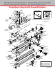
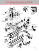
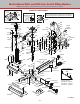
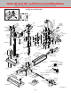
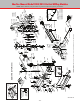
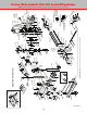
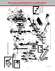
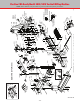
Table Of Contents
- Safety Rules for Power Tools
- An Introduction to the World of Miniature Machining
- Machine Terminology
- The Customer's Responsibility
- Learning More About Machining
- Visit the Sherline Website for the Latest Updates
- Lubrication
- Initial Assembly of a New Machine
- LATHE—Mounting the Crosslide
- All MILLS—X-Axis Handwheel Installation
- Digital Readout Handwheels
- 5000-Series Mills—Mounting the Column
- 2000- and 5800-Series Mills—Assembling and Mounting the Multi-Direction Column
- Mounting the Motor and Speed Control Unit to the Headstock
- Operation of the Motor and Electronic Speed Control
- What to Do if the Motor Suddenly Shuts Down
- Replacing Brushes on a DC Motor
- Mounting the Lathe or Mill to a Board for Stability
- Converting Machines from Inch to Metric and Vice Versa
- ADJUSTMENTS
- Two-Speed Pulley
- Spindle Preload Adjustment
- Gib Adjustment (Lathe and Mill)
- Backlash Adjustment (Lathe and Mill)
- Handwheel Adjustment (Lathe and Mill)
- Saddle Nut Adjustment (Lathe and Mill)
- Adjustment and Use of the Tailstock Gib
- Aligning the Headstock and Tailstock on the Lathe
- Squaring up Your Mill
- Use of Cutting Oils and Lubricants
- General Machining Terms
- Lathe Operating Instructions
- Digital Readouts, P/N 8200
- Live Center, P/N 1197
- Steady Rest, P/N 1074
- Thread Cutting Attachment, P/N 3100
- 3-Jaw, 4-Jaw and Drill Chucks
- Accessories for Your Lathe
- Guide to Approximate Turning Speeds
- Inserted Tip Carbide Tools
- Using the Cutoff or Parting Tool
- Tool Shapes and Grinding Your Own Cutting Tools
- Taper Turning
- Faceplate Turning
- Reaming
- Headstock Drilling
- Tailstock Drilling
- Center Drilling
- Removing Tools from the Morse Taper Spindles
- Turning Between Centers
- Holding the Workpiece
- Inducing Chatter and Learning How to Overcome It
- 3-Jaw Chuck Operation and Maintenance
- Vertical Milling Machine Operation
- Industrial Applications for Sherline Components
- Longer Tables and Taller Milling Columns Available
- Several Reasons to Consider CNC
- Learning About CNC
- CNC and CNC-Ready Sherline Lathes and Milling Machines
- CNC Rotary Indexer (P/N 8700)
- 4" Rotary Table (P/N 3700)
- Tilting Angle Table (P/N 3750)
- Mill Vise Set (P/N 3551)
- Drill Chucks (P/N 3072) and Center Drills
- Fly Cutters (P/N 3052 and P/N 7620)
- Boring Head (P/N 3054/3049)
- Mill Collet Set
- Drill Chuck Holder (P/N 3074)
- 3/8" End Mill Holder (P/N 3079)
- Accessories for Your Milling Machine
- Using the Mill Column Saddle Lock
- End Mills
- Cutting Speeds for Milling
- Determining the Depth of Cut
- Locating the Edge of a Part in Relation to the Spindle
- Using a Dial Indicator
- Standard Milling Versus Climb Milling
- Types of Milling Cutters
- Three Types of Work
- Purchasing Materials in Small Quantities
- Things to Consider Before You Start Cutting
- Locking the Axes
- Securing the Workpiece
- Helpful Tips for Milling
- General Description
- DRO Machine Operations
- Installing Stepper Motors
- Lead Wire Connection and Color Code
- Sherline Stepper Motor Specifications—Nmb Motors
- Using Handwheels on the Stepper Motors
- Stepper Motor Installation Instructions
- Sherline CNC Motor-Mounting Instructions
- Sherline Machine Technical Specifications

-52-
Sherline CNC-Ready Model 5800/5810 Vertical Milling Machine
NOTE: Where dierent, Inch part number is given rst, followed by Metric part number.
FIGURE 98
43150
43110
90060
90080
41130
43140
40620 (US)
40630 (UK)
40640 (Euro.)
41080
43180
45475
(Hill House-2020)
43120
41080
32100
43360
43460
43100
43170
43160
40440
43130
43170
40520 40660
40670
30220
40670
40660
40690
40020
43230
40040
31080
40420
40100
40420
40320
40440
40230
40330
40990
40820
40670
54182
50211
50150
40690
58011
50200/51200
40520
40690
50140/51140
50173/51173
56192/56193
40550
40820
40560
50150
40980
50211
40520
40600
40890/41890
40820
45070
40760
40600
40980
45290/45291
56230
40170/41170
40520
40600
40260
40600
40540
40160
30230
43200 (Label)
43190
40520
45261
40570
40580
56200
56400
56330
56220
50220
56210
56470
56230
56440
56240
40510
56450
40340
40330
56350
35160
35170
45040
(Nylon Button)
50920
50930
40520
44172/44173
50240
40150
44171
40780
40173
40660
40176
50211
40165
SHERLINE PRODUCTS INC. • 3235 Executive Ridge • Vista • California 92081-8527 • FAX: (760) 727-7857
Toll Free Order Line: (800) 541-0735 • International/Local/Tech. Assistance: (760) 727-5857 • Internet: www.sherline.com
Sherline CNC-Ready Model 5800/5810 NexGen Vertical Mill
NOTE: Where different, Inch part number is given first, followed by Metric part number.
Exploded View and Part Numbers
6/17/20
40520
67111
67120
67101
40520
67111
67115
12050 (3)
+ 1 zip tie
67120
671052
Mill Saddle Oiler Detail
50920
50930
40520
40520
40520
Y-Axis Slide Screw
Insert Lock Screw
X-Axis Slide Screw
Insert Lock Screw
67111
671052
67107/67109 L/H
67120
3562
67120
67111
67115
67101
12050 (3)
+ 1 zip tie
Standard Handwheels
40520
X-Axis: 40080/41040
Y-Axis: 40050/41050
Z-Axis: 3400/3410
Adjustable “Zero” Handwheels
40520
34250
34210
X-, Z-Axes: 34260/34270
Y-Axis: 34230/34240
67106/67108 (RH)
67120
67111
67120
67101
67111
40520
671052
67115
12050 (3)
+ 1 zip tie
34220
58165
56140
50056
40510
50940
50190
50130/51130
40520
40530
54183
40280
PROPER ORIENTATION OF
MOVABLE CLAMPING DISK
P/N 35170
RIGHT WRONG