
Sherline 4400 Lathes - Assembly and Instruction Guide
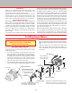
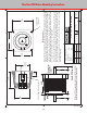
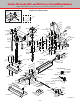
Table Of Contents
- Safety Rules for Power Tools
- An Introduction to the World of Miniature Machining
- Machine Terminology
- The Customer's Responsibility
- Learning More About Machining
- Visit the Sherline Website for the Latest Updates
- Lubrication
- Initial Assembly of a New Machine
- LATHE—Mounting the Crosslide
- All MILLS—X-Axis Handwheel Installation
- Digital Readout Handwheels
- 5000-Series Mills—Mounting the Column
- 2000- and 5800-Series Mills—Assembling and Mounting the Multi-Direction Column
- Mounting the Motor and Speed Control Unit to the Headstock
- Operation of the Motor and Electronic Speed Control
- What to Do if the Motor Suddenly Shuts Down
- Replacing Brushes on a DC Motor
- Mounting the Lathe or Mill to a Board for Stability
- Converting Machines from Inch to Metric and Vice Versa
- ADJUSTMENTS
- Two-Speed Pulley
- Spindle Preload Adjustment
- Gib Adjustment (Lathe and Mill)
- Backlash Adjustment (Lathe and Mill)
- Handwheel Adjustment (Lathe and Mill)
- Saddle Nut Adjustment (Lathe and Mill)
- Adjustment and Use of the Tailstock Gib
- Aligning the Headstock and Tailstock on the Lathe
- Squaring up Your Mill
- Use of Cutting Oils and Lubricants
- General Machining Terms
- Lathe Operating Instructions
- Digital Readouts, P/N 8200
- Live Center, P/N 1197
- Steady Rest, P/N 1074
- Thread Cutting Attachment, P/N 3100
- 3-Jaw, 4-Jaw and Drill Chucks
- Accessories for Your Lathe
- Guide to Approximate Turning Speeds
- Inserted Tip Carbide Tools
- Using the Cutoff or Parting Tool
- Tool Shapes and Grinding Your Own Cutting Tools
- Taper Turning
- Faceplate Turning
- Reaming
- Headstock Drilling
- Tailstock Drilling
- Center Drilling
- Removing Tools from the Morse Taper Spindles
- Turning Between Centers
- Holding the Workpiece
- Inducing Chatter and Learning How to Overcome It
- 3-Jaw Chuck Operation and Maintenance
- Vertical Milling Machine Operation
- Industrial Applications for Sherline Components
- Longer Tables and Taller Milling Columns Available
- Several Reasons to Consider CNC
- Learning About CNC
- CNC and CNC-Ready Sherline Lathes and Milling Machines
- CNC Rotary Indexer (P/N 8700)
- 4" Rotary Table (P/N 3700)
- Tilting Angle Table (P/N 3750)
- Mill Vise Set (P/N 3551)
- Drill Chucks (P/N 3072) and Center Drills
- Fly Cutters (P/N 3052 and P/N 7620)
- Boring Head (P/N 3054/3049)
- Mill Collet Set
- Drill Chuck Holder (P/N 3074)
- 3/8" End Mill Holder (P/N 3079)
- Accessories for Your Milling Machine
- Using the Mill Column Saddle Lock
- End Mills
- Cutting Speeds for Milling
- Determining the Depth of Cut
- Locating the Edge of a Part in Relation to the Spindle
- Using a Dial Indicator
- Standard Milling Versus Climb Milling
- Types of Milling Cutters
- Three Types of Work
- Purchasing Materials in Small Quantities
- Things to Consider Before You Start Cutting
- Locking the Axes
- Securing the Workpiece
- Helpful Tips for Milling
- General Description
- DRO Machine Operations
- Installing Stepper Motors
- Lead Wire Connection and Color Code
- Sherline Stepper Motor Specifications—Nmb Motors
- Using Handwheels on the Stepper Motors
- Stepper Motor Installation Instructions
- Sherline CNC Motor-Mounting Instructions
- Sherline Machine Technical Specifications

-44-
FINISH
MATERIAL
B
1
PART NUMBER
SHEET
TITLE
SCALE
DO NOT SCALE DRAWING !!!
SIZE REV.
2
0298
B
DRAWN
CHECKED
DECIMALS .00 . . . . . .
DECIMALS .000 . . . . . .
ANGLES . . . . . . . . . .
TOLERANCES ARE:
DESIGNER
2
A
UNLESS OTHERWISE SPECIFIED
DIMENSIONS ARE IN INCHES.
DEBURR . . . . . . . . . .
HEAT TREAT
1
STEPPER MOTOR MOUNT
1998-09
67102
SHERLINE PRODUCTS, INC.
1°
JOE MARTIN
JOE MARTIN
JOE MARTIN
1 of 1
1 = 1
BLACK ANODIZE
3 5/16 ROUND 6061 T6
HAND
NONE
±0.006
±0.003
FLANGE
BOSS
Optional rear
handwheel
shaft
.5 .46
2.13"
Shaft: .25" Diameter
A
0.515
1.501
1.502
FLAT
1.775
1.600
SET SCREW ACCESS HOLE
8–32 TAPPED
THRU 4 PL
1.857
1.857 2.250
Mounting Instructions
To mount the motor, start by turning the leadscrew until the coupling set screw lines up
with the access hole in the mount. Carefully insert the motor shaft into the coupling. With
the anges touching, rotate the stepper motor until the at on the shaft is in alignment
with the coupling set screw. Tighten the set screw. Rotate the motor to align with the
motor with the 8-32 tapped holes. We usually attach the motor using three screws and
use a zip tie in the fourth hole to secure the wire bundle.
If you decide to use LocTite® on the shaft set screw, a problem can occur if the motor
has to be removed. What can happen is the shaft ends up glued to the coupling. If this
occurs, loosen the preload nut until the motor and shaft can be backed out to expose
the coupling so you can work on it. Be careful not to ex the coupling or it can break
at the dampening slots.
If using a non-Sherline stepper motor, make sure to grind flats on the shafts
as shown where the coupling and handwheel set screws contact the shaft.
FIGURE 90
Sherline CNC Motor-Mounting Instructions