
Sherline 4400 Lathes - Assembly and Instruction Guide
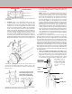
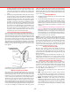
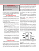
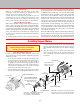
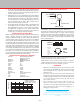
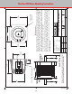
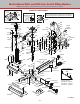
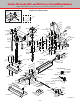
Table Of Contents
- Safety Rules for Power Tools
- An Introduction to the World of Miniature Machining
- Machine Terminology
- The Customer's Responsibility
- Learning More About Machining
- Visit the Sherline Website for the Latest Updates
- Lubrication
- Initial Assembly of a New Machine
- LATHE—Mounting the Crosslide
- All MILLS—X-Axis Handwheel Installation
- Digital Readout Handwheels
- 5000-Series Mills—Mounting the Column
- 2000- and 5800-Series Mills—Assembling and Mounting the Multi-Direction Column
- Mounting the Motor and Speed Control Unit to the Headstock
- Operation of the Motor and Electronic Speed Control
- What to Do if the Motor Suddenly Shuts Down
- Replacing Brushes on a DC Motor
- Mounting the Lathe or Mill to a Board for Stability
- Converting Machines from Inch to Metric and Vice Versa
- ADJUSTMENTS
- Two-Speed Pulley
- Spindle Preload Adjustment
- Gib Adjustment (Lathe and Mill)
- Backlash Adjustment (Lathe and Mill)
- Handwheel Adjustment (Lathe and Mill)
- Saddle Nut Adjustment (Lathe and Mill)
- Adjustment and Use of the Tailstock Gib
- Aligning the Headstock and Tailstock on the Lathe
- Squaring up Your Mill
- Use of Cutting Oils and Lubricants
- General Machining Terms
- Lathe Operating Instructions
- Digital Readouts, P/N 8200
- Live Center, P/N 1197
- Steady Rest, P/N 1074
- Thread Cutting Attachment, P/N 3100
- 3-Jaw, 4-Jaw and Drill Chucks
- Accessories for Your Lathe
- Guide to Approximate Turning Speeds
- Inserted Tip Carbide Tools
- Using the Cutoff or Parting Tool
- Tool Shapes and Grinding Your Own Cutting Tools
- Taper Turning
- Faceplate Turning
- Reaming
- Headstock Drilling
- Tailstock Drilling
- Center Drilling
- Removing Tools from the Morse Taper Spindles
- Turning Between Centers
- Holding the Workpiece
- Inducing Chatter and Learning How to Overcome It
- 3-Jaw Chuck Operation and Maintenance
- Vertical Milling Machine Operation
- Industrial Applications for Sherline Components
- Longer Tables and Taller Milling Columns Available
- Several Reasons to Consider CNC
- Learning About CNC
- CNC and CNC-Ready Sherline Lathes and Milling Machines
- CNC Rotary Indexer (P/N 8700)
- 4" Rotary Table (P/N 3700)
- Tilting Angle Table (P/N 3750)
- Mill Vise Set (P/N 3551)
- Drill Chucks (P/N 3072) and Center Drills
- Fly Cutters (P/N 3052 and P/N 7620)
- Boring Head (P/N 3054/3049)
- Mill Collet Set
- Drill Chuck Holder (P/N 3074)
- 3/8" End Mill Holder (P/N 3079)
- Accessories for Your Milling Machine
- Using the Mill Column Saddle Lock
- End Mills
- Cutting Speeds for Milling
- Determining the Depth of Cut
- Locating the Edge of a Part in Relation to the Spindle
- Using a Dial Indicator
- Standard Milling Versus Climb Milling
- Types of Milling Cutters
- Three Types of Work
- Purchasing Materials in Small Quantities
- Things to Consider Before You Start Cutting
- Locking the Axes
- Securing the Workpiece
- Helpful Tips for Milling
- General Description
- DRO Machine Operations
- Installing Stepper Motors
- Lead Wire Connection and Color Code
- Sherline Stepper Motor Specifications—Nmb Motors
- Using Handwheels on the Stepper Motors
- Stepper Motor Installation Instructions
- Sherline CNC Motor-Mounting Instructions
- Sherline Machine Technical Specifications

-43-
4. Insert the motor shaft into the coupling, making sure the
set screw is aligned with the at. Keep the motor square to
the mount so as not to ex the coupling during insertion.
Loosely tighten the set screw.
5. Install three 8-32 x 3/8" socket head cap screws (SHCS)
through the holes in the motor ange and into the stepper
motor mount holes. Instead of a 4th screw in the four
o’clock position use a tie wrap through that hole to secure
the wire bundle from the motor. This will help relieve
strain on the motor plug connection.
6. Assure that the at on the motor shaft is still aligned with
the coupling set screw (observe the position of the rear
at or handwheel set screw—the two ats are parallel)
and tighten the coupling set screw. Install and turn the
handwheel and observe the movement of the leadscrew
to make sure everything is turning smoothly.
Using Handwheels on the Stepper Motors
When turning an unpowered stepper motor by hand you may
notice a slightly “notchy” feel because of the permanent
magnets in the motor. This is normal. When the motors are
powered up they lock in position, and it will be very dicult
to move them with the handwheels. Therefore, if you wish to
use manual mode, you should rst turn o the power to the
motors using the ON/OFF switch on the external driver box or
on the side of the computer if the driver box is built in. Turning
a DC motor by hand causes it to act as a generator, sending
current backward through the circuit. However, low amounts
of current will not damage the board, so avoid cranking faster
than about 1 rev/sec to be safe. For longer travels, use EMC’s
jog mode for approximate positioning, then turn o driver box
power and use the handwheel for ne tuning.
Sherline Stepper Motor Specifications—Nmb Motors
Sherline P/N: 67127 (w/ DIN plug and flats of shaft)
67130 (no plug, flats on shaft)
Manufacturer: NMB (Minebea Co. Ltd.)
Mfg. P/N (Type): 23KM-K035-62V (double shaft)
Frame size: NEMA #23
Step angle: 1.8°
Voltage: 3.2 V
Current: 2.0 A/F
Resistance: 1.6 W/F
Inductance: 3.6 mH/F
Holding torque: 9.7 kg-cm
Rotor inertia: 250 g-cm
2
Number of wire leads: 6 (See color code diagram FIG. 2)
Weight: 1.32 lb (0.6 Kg.)
Length: 2.13" (54 mm)
Shaft: Double ended, 1/4" diameter
DRIVER : TYPE B(Vs=24V)
CURRENT=2.0A/Phase
EXCITING MODE=2Phase
INERTIAL LOAD : 100g-cm
2
FREQUENCY (pps)
TORQUE (kgf-cm)
12.0
10.0
8.0
6.0
4.0
2.0
0 1000 2000 3000 4000 5000
Figure 87—Motor torque curve
Lead Wire Connection and Color Code
RED (+A)
BLACK (COM A)
YELLOW (-A)
BLUE (+B)
WHITE (COM B)
ORANGE (-B)
FIGURE 88— Color of internal wiring for NMB motors
See Figure 89 for the pin diagram and wire color layout of the
stepper motor connector cables we supply with our stepper
motors. Since there is no industry standard for wire colors in
this eld, if using a connector not supplied by Sherline each
pin and color should be conrmed with a continuity tester
before applying power.
1 2 3 4 5 6
SEEN FROM TOP
OF MOTOR PLUG
SEEN FROM
OUTSIDE OF
MALE
CONNECTOR
6
4
2 + 5
3
1
color codes are:
1 = Orange
2 = Black
3 = Blue
4 = Yellow
5 = White (or tan)
6 = Red
FIGURE 89: diagram shows which pin in the DIN connector is
wired to which position in the motor connector.
NOTE: Motors can be wired in either unipolar or bipolar
conguration depending on how the leads are connected. Sherline
motors with plugs are wired for unipolar operation.
PRECAUTIONS
• Make sure the ends of raw wires are not touching each other
when turning the handwheel by hand to drive the stepper
motor and leadscrew. It can cause the motor to feel rough
and hard to turn.
• DC motors generate current when hand cranked that can
damage the control unit. When positioning a stepper motor
by hand using the handwheel, do not crank faster than about
1 rev/second. For long travels, use the jog mode of your
CNC control software.
• Poor connections can cause arcing, which can burn out
motors or control chips. Always make sure plugs and
connections are fully engaged and making good contact.
• Always turn o driver box power before plugging in or
unplugging a stepper motor.
“A man who works with his hands is a laborer.
A man who works with his hands and his brain is a craftsman.
A man who works with his hands, his brain and his heart is an artist.”
—Louis Nizer