
Sherline 4400 Lathes - Assembly and Instruction Guide
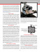
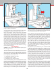

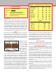
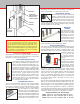
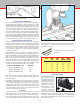
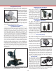
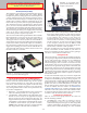
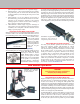
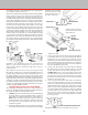
Table Of Contents
- Safety Rules for Power Tools
- An Introduction to the World of Miniature Machining
- Machine Terminology
- The Customer's Responsibility
- Learning More About Machining
- Visit the Sherline Website for the Latest Updates
- Lubrication
- Initial Assembly of a New Machine
- LATHE—Mounting the Crosslide
- All MILLS—X-Axis Handwheel Installation
- Digital Readout Handwheels
- 5000-Series Mills—Mounting the Column
- 2000- and 5800-Series Mills—Assembling and Mounting the Multi-Direction Column
- Mounting the Motor and Speed Control Unit to the Headstock
- Operation of the Motor and Electronic Speed Control
- What to Do if the Motor Suddenly Shuts Down
- Replacing Brushes on a DC Motor
- Mounting the Lathe or Mill to a Board for Stability
- Converting Machines from Inch to Metric and Vice Versa
- ADJUSTMENTS
- Two-Speed Pulley
- Spindle Preload Adjustment
- Gib Adjustment (Lathe and Mill)
- Backlash Adjustment (Lathe and Mill)
- Handwheel Adjustment (Lathe and Mill)
- Saddle Nut Adjustment (Lathe and Mill)
- Adjustment and Use of the Tailstock Gib
- Aligning the Headstock and Tailstock on the Lathe
- Squaring up Your Mill
- Use of Cutting Oils and Lubricants
- General Machining Terms
- Lathe Operating Instructions
- Digital Readouts, P/N 8200
- Live Center, P/N 1197
- Steady Rest, P/N 1074
- Thread Cutting Attachment, P/N 3100
- 3-Jaw, 4-Jaw and Drill Chucks
- Accessories for Your Lathe
- Guide to Approximate Turning Speeds
- Inserted Tip Carbide Tools
- Using the Cutoff or Parting Tool
- Tool Shapes and Grinding Your Own Cutting Tools
- Taper Turning
- Faceplate Turning
- Reaming
- Headstock Drilling
- Tailstock Drilling
- Center Drilling
- Removing Tools from the Morse Taper Spindles
- Turning Between Centers
- Holding the Workpiece
- Inducing Chatter and Learning How to Overcome It
- 3-Jaw Chuck Operation and Maintenance
- Vertical Milling Machine Operation
- Industrial Applications for Sherline Components
- Longer Tables and Taller Milling Columns Available
- Several Reasons to Consider CNC
- Learning About CNC
- CNC and CNC-Ready Sherline Lathes and Milling Machines
- CNC Rotary Indexer (P/N 8700)
- 4" Rotary Table (P/N 3700)
- Tilting Angle Table (P/N 3750)
- Mill Vise Set (P/N 3551)
- Drill Chucks (P/N 3072) and Center Drills
- Fly Cutters (P/N 3052 and P/N 7620)
- Boring Head (P/N 3054/3049)
- Mill Collet Set
- Drill Chuck Holder (P/N 3074)
- 3/8" End Mill Holder (P/N 3079)
- Accessories for Your Milling Machine
- Using the Mill Column Saddle Lock
- End Mills
- Cutting Speeds for Milling
- Determining the Depth of Cut
- Locating the Edge of a Part in Relation to the Spindle
- Using a Dial Indicator
- Standard Milling Versus Climb Milling
- Types of Milling Cutters
- Three Types of Work
- Purchasing Materials in Small Quantities
- Things to Consider Before You Start Cutting
- Locking the Axes
- Securing the Workpiece
- Helpful Tips for Milling
- General Description
- DRO Machine Operations
- Installing Stepper Motors
- Lead Wire Connection and Color Code
- Sherline Stepper Motor Specifications—Nmb Motors
- Using Handwheels on the Stepper Motors
- Stepper Motor Installation Instructions
- Sherline CNC Motor-Mounting Instructions
- Sherline Machine Technical Specifications

-38-
with sucient accuracy while maintaining a price appropriate
for a machine of this size and cost.
The kit can be installed on any Sherline lathe or mill, regardless
of age, and is very easy to use. Three axes of movement are
provided so the readout can be used when the lathe is set up
as a mill with the optional vertical milling column attachment.
In the lathe conguration you will use only two of the three,
as the tailstock spindle feed screw is not tted with a readout.
Remember that the directions of movement of the mill are
referred to as the X-axis (table side-to-side), Y-axis (table
in-out) and Z-axis (spindle up-down) when seen from the
leadscrew handwheel end of the lathe. When used as a lathe, the
nomenclature changes slightly. The crosslide feed handwheel
still controls what is called the “X” axis, but the leadscrew
controls what is now called the “Z” axis. Remember also that
as you feed the cutter into the rotating part with the crosslide
handwheel you will reduce the diameter of the part by twice
the amount of the feed. This is because you are reducing the
part’s radius but measuring its diameter. This DRO measures
the change in radius.
(Crosslide)
FIGURE 77—The designations of the axes of movement are
dierent in lathe and mill congurations. A lathe used with a
vertical milling column is considered a mill when it comes to
naming the axes.
(Leadscrew)
The readout of any axis can be set to zero at any time with
the push of a button. As you move the handwheels you can
read the table position to three and a half decimal places on
the digital readout. It is not necessary to keep track of the
number of handwheel rotations to gure the stopping point on
larger dimensions. This will be especially appreciated when
cranking in “negative” amounts. Backlash is compensated for
by setting it into the unit’s electronic memory in increments
of .0005". As a bonus, the package also includes an electronic
readout of spindle RPM at all times.
Installing the DRO Components on Your Sherline Machine
The following instructions describe the steps required to
remove the existing handwheels and thrust collars and replace
them with the DRO encoder/handwheel units.
1. LATHE: Move the crosslide all the way in. This will help
locate the slide screw to assure that the collar is centered.
The saddle can be positioned anywhere on the leadscrew.
MILL: Move the table all the way to the left. This will
limit movement of the leadscrew and help center the
new collar. Then move the table all the way to the front
toward the operator.
2. Raise the headstock all the way up to the top of its travel
on you mill. Do the same if you are using a vertical milling
column on a lathe.
3. Using a 3/32" hex wrench, remove all three handwheels
by releasing their set screws and sliding them o their
leadscrews. (If your machine has resettable “zero”
handwheels, loosen the collar locking knob and rotate the
collar until the hole lines up with the set screw. Then use
the 3/32" hex wrench to loosen the set screw and remove
the entire handwheel/collar unit.)
4. Using a 3/32" hex wrench, remove the 5-40 screw holding
the thrust collar over the crosslide (lathe), or X- and
Y-axes (mill) and remove the collar. (See Figure 78A.)
LATHE ONLY: Use a 1/8" hex wrench to remove the
countersunk screw in the top of the lathe bed and a 5/32"
hex wrench to remove the socket head cap screw under
the lathe base so that the collar can be removed from the
leadscrew. (See Figure 78B.)
5. Clean each grooved thrust collar with a solvent like
acetone or lacquer thinner to remove any oil from the
surface. (You will later lock them in place in relation to the
plastic housing with “instant glue” and the glue will not
stick to an oily collar.) Using the existing screws, install
new grooved thrust collars on the X- and Y-axes, making
sure the leadscrew is centered in the collar. Make sure
the screws are secure, but do not overtighten. If a shim
washer was present on your existing leadscrew, reinstall
it as it was before.
FIGURE 78A—Installing
the new thrust collar on the
lathe crosslide screw, or on
the mill X- and Y-axes.
THRUST COLLAR, P/N 8130
EXISTING SCREW
LEADSCREW SHOULDER
LEADSCREW
FIGURE 78B—Installing
the new thrust collar on the
lathe leadscrew.
EXISTING SCREW
AND WASHER OR
WASHERS
LEADSCREW
EXISTING WASHER
EXISTING SCREW
THRUST COLLAR, P/N 81508
LATHE BED
FIGURE 79—Making sure the crosslide screw is centered
CENTER THE SLIDE SCREW BEFORE TIGHTENING SCREW