
Sherline 4400 Lathes - Assembly and Instruction Guide
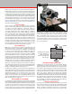
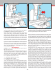

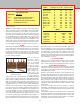
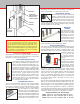
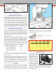
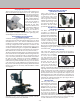
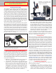
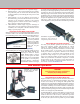
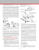
Table Of Contents
- Safety Rules for Power Tools
- An Introduction to the World of Miniature Machining
- Machine Terminology
- The Customer's Responsibility
- Learning More About Machining
- Visit the Sherline Website for the Latest Updates
- Lubrication
- Initial Assembly of a New Machine
- LATHE—Mounting the Crosslide
- All MILLS—X-Axis Handwheel Installation
- Digital Readout Handwheels
- 5000-Series Mills—Mounting the Column
- 2000- and 5800-Series Mills—Assembling and Mounting the Multi-Direction Column
- Mounting the Motor and Speed Control Unit to the Headstock
- Operation of the Motor and Electronic Speed Control
- What to Do if the Motor Suddenly Shuts Down
- Replacing Brushes on a DC Motor
- Mounting the Lathe or Mill to a Board for Stability
- Converting Machines from Inch to Metric and Vice Versa
- ADJUSTMENTS
- Two-Speed Pulley
- Spindle Preload Adjustment
- Gib Adjustment (Lathe and Mill)
- Backlash Adjustment (Lathe and Mill)
- Handwheel Adjustment (Lathe and Mill)
- Saddle Nut Adjustment (Lathe and Mill)
- Adjustment and Use of the Tailstock Gib
- Aligning the Headstock and Tailstock on the Lathe
- Squaring up Your Mill
- Use of Cutting Oils and Lubricants
- General Machining Terms
- Lathe Operating Instructions
- Digital Readouts, P/N 8200
- Live Center, P/N 1197
- Steady Rest, P/N 1074
- Thread Cutting Attachment, P/N 3100
- 3-Jaw, 4-Jaw and Drill Chucks
- Accessories for Your Lathe
- Guide to Approximate Turning Speeds
- Inserted Tip Carbide Tools
- Using the Cutoff or Parting Tool
- Tool Shapes and Grinding Your Own Cutting Tools
- Taper Turning
- Faceplate Turning
- Reaming
- Headstock Drilling
- Tailstock Drilling
- Center Drilling
- Removing Tools from the Morse Taper Spindles
- Turning Between Centers
- Holding the Workpiece
- Inducing Chatter and Learning How to Overcome It
- 3-Jaw Chuck Operation and Maintenance
- Vertical Milling Machine Operation
- Industrial Applications for Sherline Components
- Longer Tables and Taller Milling Columns Available
- Several Reasons to Consider CNC
- Learning About CNC
- CNC and CNC-Ready Sherline Lathes and Milling Machines
- CNC Rotary Indexer (P/N 8700)
- 4" Rotary Table (P/N 3700)
- Tilting Angle Table (P/N 3750)
- Mill Vise Set (P/N 3551)
- Drill Chucks (P/N 3072) and Center Drills
- Fly Cutters (P/N 3052 and P/N 7620)
- Boring Head (P/N 3054/3049)
- Mill Collet Set
- Drill Chuck Holder (P/N 3074)
- 3/8" End Mill Holder (P/N 3079)
- Accessories for Your Milling Machine
- Using the Mill Column Saddle Lock
- End Mills
- Cutting Speeds for Milling
- Determining the Depth of Cut
- Locating the Edge of a Part in Relation to the Spindle
- Using a Dial Indicator
- Standard Milling Versus Climb Milling
- Types of Milling Cutters
- Three Types of Work
- Purchasing Materials in Small Quantities
- Things to Consider Before You Start Cutting
- Locking the Axes
- Securing the Workpiece
- Helpful Tips for Milling
- General Description
- DRO Machine Operations
- Installing Stepper Motors
- Lead Wire Connection and Color Code
- Sherline Stepper Motor Specifications—Nmb Motors
- Using Handwheels on the Stepper Motors
- Stepper Motor Installation Instructions
- Sherline CNC Motor-Mounting Instructions
- Sherline Machine Technical Specifications

-33-
COLUMN LEADSCREW
LOCKING LEVER—
TURN LEVER COUNTER-
CLOCKWISE TO LOCK,
CLOCKWISE TO RELEASE
FIGURE 66—Mill column saddle lock
SADDLE NUT
MILL SADDLE
LEADSCREW
SADDLE NUT
ADJUSTMENT
SET SCREWS
Sensitive Drill Attachment (P/N 1012)
The sensitive drilling attachment provides both
faster drilling of multiple holes and better “feel”
for the cut when using drills smaller than 1/16".
This is essential to keep from breaking tiny drill
bits that can be quite expensive. A Jacobs 5/32"
drill chuck is tted to a spring-loaded shaft that
inserts into the spindle. A red knurled collar with a
ball bearing at the center, allows the user to hand
feed the chuck. A spring inside the brass tube
helps return the chuck to the up position when
done. The chuck holds drills from 5/32" (4 mm)
down to much smaller sizes. The attachment is
easily installed by screwing it onto the external
3/4-16 thread of the spindle.
3/8" End Mill Holder (P/N 3079)
The 3/8" end mill holder makes it easy to use the popular
(and less expensive) 3/8" end mills. Using double-ended
end mills is economical and easy with this holder, as tools
are changed by simply loosening a set screw and changing
the tool. Sherline now oers similar
holders for other size cutting tools as
well. For CNC use, these holders allow
for quick tool changes and unlike when
using collets, the cutter length does not
change. The following additional sizes
are available: 1/8" (P/N 6081), 3/16"
Accessories for Your Milling Machine
The addition of accessories can greatly enhance the utility of
your mill. A few of the more popular milling accessories and
how they are used are described below.
(P/N 6080), 1/4" (P/N 6079), 5/16" (P/N 3075), 6.0 mm (P/N
3076), 8.0 mm (P/N 3077) and 10 mm (P/N 3078).
Drill Chuck Holder (P/N 3074)
In order to allow for a quick way to change
chucks, a similar holder with a 3/8-24
threaded boss on the end instead of a hole
is now available. This allows 1/4" and 3/8"
Jacobs drill chucks to be threaded onto
a holder and changed quickly. During CNC operations this
also means drills can be changed without having to change
the tool length in the “tools” table.
Machining Tip
Use of a tooling plate (P/N 3560) is an inexpensive
way to protect the surface of your mill table while
providing a at, versatile clamping surface with a pre-
drilled pattern of tapped holes for mounting parts and
xtures. The additional thickness also adds rigidity to
the mill table. A round tooling plate is also available
for the rotary table (P/N 3725).
Mill Collet Set
(P/N 3060)
The main purpose of the
mill collet set is to hold
single-ended end mills
accurately on center.
The spindle nose has an
internal Morse #1 taper
that closes the collet as
the drawbolt is tightened.
Mill collets are available individually or in sets of the three
most common sizes with a drawbolt included.
Boring Head (P/N 3054/3049)
The main purpose of the boring head is to eliminate the need
for a large inventory of drills and reamers. A small milling
machine would not have the power or rigidity to turn a one-
inch diameter drill even if one could be obtained that would
t. However, holes of up
to 1-3/4" (44 mm) can
be accurately bored to
size with a little patience
and care.
Boring heads for the mill
work on the same cutting
principle as lathe boring,
except that the cutting
tool turns while the work
remains stationary. (In
the case of a lathe, the work turns and the cutter remains
stationary.) The boring head is designed to employ round
cutting tools with a 3/8" shank. Sherline oers three boring
tools with sizes and lengths appropriate for the Sherline
mill. It is sometimes advisable to remove excessive tool
shank length from standard (non-Sherline) 3/8" boring tools
in order to improve rigidity. (See Figure 58, page 30 for a
boring tool in use.)
Tool sizes are listed indicating the smallest diameter hole
that can be bored and the maximum depth that can be cut.
For best results, use the largest diameter possible with the
shortest lengths. A .010" cut represents a good starting point.
If boring a hole where a at bottom is required, it is advisable
to stop the down-feed at about .002" above the desired depth,
turn o the motor and cut the remaining distance by hand-
turning the spindle to eliminate any possibility of chatter.
Boring Tools Available—3/8" diameter shanks
P/N 3061—Min. hole size: 1/4" (6.4 mm), Max. depth: 0.6" (15 mm.)
P/N 3063—Min. hole size: 5/16" (7.9 mm), Max. depth: 1.0" (25 mm)
P/N 3064—Min. hole size: 5/16" (7.9 mm), Max. depth: 1.5" (38.1 mm)
BORING TOOL
BORING HEAD