
Sherline 4400 Lathes - Assembly and Instruction Guide
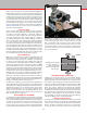
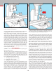

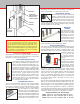
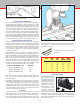
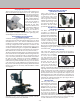
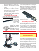
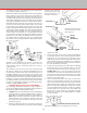
Table Of Contents
- Safety Rules for Power Tools
- An Introduction to the World of Miniature Machining
- Machine Terminology
- The Customer's Responsibility
- Learning More About Machining
- Visit the Sherline Website for the Latest Updates
- Lubrication
- Initial Assembly of a New Machine
- LATHE—Mounting the Crosslide
- All MILLS—X-Axis Handwheel Installation
- Digital Readout Handwheels
- 5000-Series Mills—Mounting the Column
- 2000- and 5800-Series Mills—Assembling and Mounting the Multi-Direction Column
- Mounting the Motor and Speed Control Unit to the Headstock
- Operation of the Motor and Electronic Speed Control
- What to Do if the Motor Suddenly Shuts Down
- Replacing Brushes on a DC Motor
- Mounting the Lathe or Mill to a Board for Stability
- Converting Machines from Inch to Metric and Vice Versa
- ADJUSTMENTS
- Two-Speed Pulley
- Spindle Preload Adjustment
- Gib Adjustment (Lathe and Mill)
- Backlash Adjustment (Lathe and Mill)
- Handwheel Adjustment (Lathe and Mill)
- Saddle Nut Adjustment (Lathe and Mill)
- Adjustment and Use of the Tailstock Gib
- Aligning the Headstock and Tailstock on the Lathe
- Squaring up Your Mill
- Use of Cutting Oils and Lubricants
- General Machining Terms
- Lathe Operating Instructions
- Digital Readouts, P/N 8200
- Live Center, P/N 1197
- Steady Rest, P/N 1074
- Thread Cutting Attachment, P/N 3100
- 3-Jaw, 4-Jaw and Drill Chucks
- Accessories for Your Lathe
- Guide to Approximate Turning Speeds
- Inserted Tip Carbide Tools
- Using the Cutoff or Parting Tool
- Tool Shapes and Grinding Your Own Cutting Tools
- Taper Turning
- Faceplate Turning
- Reaming
- Headstock Drilling
- Tailstock Drilling
- Center Drilling
- Removing Tools from the Morse Taper Spindles
- Turning Between Centers
- Holding the Workpiece
- Inducing Chatter and Learning How to Overcome It
- 3-Jaw Chuck Operation and Maintenance
- Vertical Milling Machine Operation
- Industrial Applications for Sherline Components
- Longer Tables and Taller Milling Columns Available
- Several Reasons to Consider CNC
- Learning About CNC
- CNC and CNC-Ready Sherline Lathes and Milling Machines
- CNC Rotary Indexer (P/N 8700)
- 4" Rotary Table (P/N 3700)
- Tilting Angle Table (P/N 3750)
- Mill Vise Set (P/N 3551)
- Drill Chucks (P/N 3072) and Center Drills
- Fly Cutters (P/N 3052 and P/N 7620)
- Boring Head (P/N 3054/3049)
- Mill Collet Set
- Drill Chuck Holder (P/N 3074)
- 3/8" End Mill Holder (P/N 3079)
- Accessories for Your Milling Machine
- Using the Mill Column Saddle Lock
- End Mills
- Cutting Speeds for Milling
- Determining the Depth of Cut
- Locating the Edge of a Part in Relation to the Spindle
- Using a Dial Indicator
- Standard Milling Versus Climb Milling
- Types of Milling Cutters
- Three Types of Work
- Purchasing Materials in Small Quantities
- Things to Consider Before You Start Cutting
- Locking the Axes
- Securing the Workpiece
- Helpful Tips for Milling
- General Description
- DRO Machine Operations
- Installing Stepper Motors
- Lead Wire Connection and Color Code
- Sherline Stepper Motor Specifications—Nmb Motors
- Using Handwheels on the Stepper Motors
- Stepper Motor Installation Instructions
- Sherline CNC Motor-Mounting Instructions
- Sherline Machine Technical Specifications

-31-
FIGURE 60—Indicating in the center of a hole.
FIGURE 62—Indicating in a 30° head tilt using a mill vise and
draftsman’s triangle
any error (which should be small), place a shim between the
column block and the mill base.
Locating the Edge of a Part in Relation to the Spindle
There are two quick methods of “picking up an edge” of a
part on a mill. The rst is to put a shaft of known diameter in
the spindle and see that it runs perfectly true. Using a depth
micrometer against the edge of the part, measure the distance
to the outside diameter of the shaft. To that dimension add half
the known shaft diameter. You now have the distance from
the edge of the part to the centerline of the spindle. Rotate
the handwheel on the axis being set exactly this distance and
you will have the centerline of the spindle lined up with the
edge of the part from which you measured.
The second method is much easier. It involves the use of a
clever tool called an “edge nder.” These devices have been
around for years and have two lapped surfaces held together
by a spring. One surface is on the end of a shaft that ts in
a 3/8" end mill holder and is held
in the spindle. The other is a .200"
diameter shaft held to the larger shaft
with a spring so it is free to slide
around. With the spindle running
at approximately 2000 RPM, the
shorter shaft will be running way o
center. As this shaft is brought into
contact with the edge you are trying
to locate in relation to the spindle,
the .200" shaft will be tapped to the
center as the spindle rotates. This
keeps making the .200" shaft run
continually truer. When the shaft
runs perfectly true it makes contact
with the part 100% of the time. This
creates a drag on the surface of the
shaft that will “kick” it o center.
(See Figure 61.) At this point you
know the part is exactly .100" (half
FIGURE 61—Using
an “edge nder” to
accurately locate the
edge of a part.
3/8" SHAFT
SPINDLE
PART
.200" DIA. SHAFT
the diameter) from the centerline of the spindle. Advancing
the handwheel on a Sherline mill two revolutions (.050" per
revolution) will bring the edge of the part into alignment with
the spindle.
It is important to use a high quality edge nder such as the
Starrett 827A shown in the drawing. It must have a 3/8" shaft
to t the end mill holder on the Sherline mill. Metric sized
edge nders are also available which work in the same manner.
For those who like to own the newest gadgets, electronic
edge nders are now available. Import models are available
for less than $100.00.
Determining the Depth of Cut
There are no rm rules other than common sense for
determining depth of cut. A .030" cut depth with a 3/16" end
mill in aluminum could be considered light, but .003" cut
depth in steel with a 1/32" diameter end mill would break the
cutter. Start with very light cuts and gradually increase the
depth until satisfactory results are achieved. Try to develop
the skill of knowing how much of a cut is satisfactory without
breaking the cutter or damaging the work.
Note that regular end mills should not be used for drilling,
however, they may be employed to enlarge an existing hole.
The cutting edges deserve more respect than those of drills
even though similar in appearance; they are designed to cut
with their sides. Handle and store them with care.
Work Accurately
It should be remembered that a good machinist is capable
of making a part to much closer tolerances than those of the
machine with which he is working. The accuracy of the parts
you make is limited only by your skill as a craftsman and the
quality of your measurement equipment. Accuracy should be
the ultimate goal of every machinist!