
Sherline 4400 Lathes - Assembly and Instruction Guide
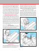
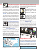
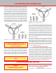
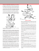
Table Of Contents
- Safety Rules for Power Tools
- An Introduction to the World of Miniature Machining
- Machine Terminology
- The Customer's Responsibility
- Learning More About Machining
- Visit the Sherline Website for the Latest Updates
- Lubrication
- Initial Assembly of a New Machine
- LATHE—Mounting the Crosslide
- All MILLS—X-Axis Handwheel Installation
- Digital Readout Handwheels
- 5000-Series Mills—Mounting the Column
- 2000- and 5800-Series Mills—Assembling and Mounting the Multi-Direction Column
- Mounting the Motor and Speed Control Unit to the Headstock
- Operation of the Motor and Electronic Speed Control
- What to Do if the Motor Suddenly Shuts Down
- Replacing Brushes on a DC Motor
- Mounting the Lathe or Mill to a Board for Stability
- Converting Machines from Inch to Metric and Vice Versa
- ADJUSTMENTS
- Two-Speed Pulley
- Spindle Preload Adjustment
- Gib Adjustment (Lathe and Mill)
- Backlash Adjustment (Lathe and Mill)
- Handwheel Adjustment (Lathe and Mill)
- Saddle Nut Adjustment (Lathe and Mill)
- Adjustment and Use of the Tailstock Gib
- Aligning the Headstock and Tailstock on the Lathe
- Squaring up Your Mill
- Use of Cutting Oils and Lubricants
- General Machining Terms
- Lathe Operating Instructions
- Digital Readouts, P/N 8200
- Live Center, P/N 1197
- Steady Rest, P/N 1074
- Thread Cutting Attachment, P/N 3100
- 3-Jaw, 4-Jaw and Drill Chucks
- Accessories for Your Lathe
- Guide to Approximate Turning Speeds
- Inserted Tip Carbide Tools
- Using the Cutoff or Parting Tool
- Tool Shapes and Grinding Your Own Cutting Tools
- Taper Turning
- Faceplate Turning
- Reaming
- Headstock Drilling
- Tailstock Drilling
- Center Drilling
- Removing Tools from the Morse Taper Spindles
- Turning Between Centers
- Holding the Workpiece
- Inducing Chatter and Learning How to Overcome It
- 3-Jaw Chuck Operation and Maintenance
- Vertical Milling Machine Operation
- Industrial Applications for Sherline Components
- Longer Tables and Taller Milling Columns Available
- Several Reasons to Consider CNC
- Learning About CNC
- CNC and CNC-Ready Sherline Lathes and Milling Machines
- CNC Rotary Indexer (P/N 8700)
- 4" Rotary Table (P/N 3700)
- Tilting Angle Table (P/N 3750)
- Mill Vise Set (P/N 3551)
- Drill Chucks (P/N 3072) and Center Drills
- Fly Cutters (P/N 3052 and P/N 7620)
- Boring Head (P/N 3054/3049)
- Mill Collet Set
- Drill Chuck Holder (P/N 3074)
- 3/8" End Mill Holder (P/N 3079)
- Accessories for Your Milling Machine
- Using the Mill Column Saddle Lock
- End Mills
- Cutting Speeds for Milling
- Determining the Depth of Cut
- Locating the Edge of a Part in Relation to the Spindle
- Using a Dial Indicator
- Standard Milling Versus Climb Milling
- Types of Milling Cutters
- Three Types of Work
- Purchasing Materials in Small Quantities
- Things to Consider Before You Start Cutting
- Locking the Axes
- Securing the Workpiece
- Helpful Tips for Milling
- General Description
- DRO Machine Operations
- Installing Stepper Motors
- Lead Wire Connection and Color Code
- Sherline Stepper Motor Specifications—Nmb Motors
- Using Handwheels on the Stepper Motors
- Stepper Motor Installation Instructions
- Sherline CNC Motor-Mounting Instructions
- Sherline Machine Technical Specifications

-28-
Securing the Workpiece
The rst problem encountered will be holding the work
and aligning it to the machine. It is important for reasons of
safety and accuracy that the workpiece be solidly secured.
This may be the most dicult task, since once the work is
clamped in position, the method of doing the entire job has
been established. Usually, a rectangular block can be easily
held in a mill vise. Note that round stock may also be held
in a “V” shaped vise slot. Mill vises are specially designed
to pull the movable jaw downward as they tighten on it. (See
Mill Vise P/N 3551 shown on page 34 and in the Sherline
Tools and Accessories Catalog.)
Certain objects can be secured with a 4-jaw lathe chuck, which
is, in turn, clamped to the machine. Some irregular shapes
such as castings may present greater diculties. Often they
may be clamped directly to the table. Very small or irregular
shapes can be secured by epoxying them to a second, more
easily held piece of material. They are broken loose after
machining. A mill tooling plate (P/N 3560) is a very useful
xture for holding parts. It has a number of holes pre-drilled
for holding clamps, and additional holes can be drilled and
tapped as needed. It also provides additional stiness and
protection for your mill table.
Locking the Axes
To keep the table from moving in a particular direction during
an operation, there is a lock available on each axis. To lock
the X-axis table from moving side-to-side there is a barrel
lock on the front of the saddle. (See Figure 55.) The Saddle is
locked by means of a thumbscrew on the left side that presses
a nylon plug against the gib to pull the saddle tight against the
dovetail. The Z-axis can be locked during milling operations
by means of a brass lever that tightens against the saddle nut
on the back of the column. (See Figure 66, page 33.)
Things to Consider Before You Start Cutting
The following steps should be considered before commencing
any part:
• Is the material about to be machined best suited for the
job, and is it machinable with available cutting tools and
equipment? Work with aluminum, brass, plastic or cast iron
whenever possible. Too often a hobbyist will pick up the
rst correctly-sized piece of material he nds at his local
salvage dealer thinking that, if it is rusty, it’s steel, and that
all steels are pretty much the same. Not so! Anyone who
has ever tried to machine an old automobile axle can attest
to this. If the part must be steel, grade 12L14, commonly
called “lead-loy,” is about the best material for machining.
It was developed for screw-machine use and is available in
round stock only. However, it works so well that many times
it may be advisable to machine rectangular parts from it. It
can also be case hardened. Your local screw-machine shop
will usually have scrap pieces available and may be a good
source for obtaining it.
• Avoid exotic materials, such as stainless steel, unless
absolutely necessary because of machining diculty and
poor milling cutter life. (If each new mechanical engineer
were given a block of stainless steel to mill, drill and tap
upon his graduation, stainless steel sales would probably
drop considerably!)
•
Before beginning, carefully study the part to be machined.
Select the best surface from which to work (usually the
attest).
• Decide if work should be “rough cut” to size. Some materials
will warp while being machined. Close tolerance parts can
be ruined by attempting heavy machining at the end of the
job rather than at the beginning.
• The method of holding the work is also determined by the
type of machining to be performed. For instance, work that
involves only small drilling jobs does not have to be held
as securely as work to be milled.
• Lay the job out so that it can be machined with the minimum
number of setups.
• Be sure to have all needed cutting tools available before
beginning a job.
• Do not start o with a job so complex that the odds of success
are limited. Making complex machined parts requires a great
deal of intelligence, planning and skill. Skill is acquired only
through experience.
In summary, you should be aware of the fact that milling
is difficult, but not impossible. There are many more
considerations than just moving the handwheels, and you
should not start your rst step until your last step has been
determined.
Purchasing Materials in Small Quantities
Commercial metal suppliers are not set up to serve the
home shop machinist. They usually have large minimum
order quantities and high “cutting charge” fees that make it
impractical to purchase small amounts from them. However,
there are now a number of suppliers that cater to the hobby
market. They have complete catalogs of the materials most
commonly used by hobbyists, and you can order as much or as
FIGURE 55—Large or odd shaped parts are usually clamped
to the mill table as shown here. Smaller parts can be held in a
milling vise. Here a center drill is used to accurately locate the
holes to be drilled in a clamped part.
P/N 3012 HOLD-DOWN
SET SHOWN. A NEWER
P/N 3013 STEP BLOCK
HOLD-DOWN SET IS NOW
ALSO AVAILABLE
TABLE LOCK
SADDLE LOCK
(NOW A THUMBSCREW)
CAUTION! Because the tool spins on a mill, hot chips can be
thrown much farther than when using a lathe. Safety glasses
and proper clothing are a must for all milling operations.