
Sherline 4400 Lathes - Assembly and Instruction Guide
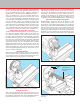
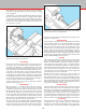
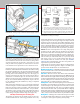
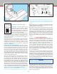
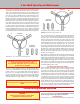
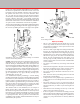
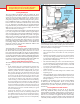
Table Of Contents
- Safety Rules for Power Tools
- An Introduction to the World of Miniature Machining
- Machine Terminology
- The Customer's Responsibility
- Learning More About Machining
- Visit the Sherline Website for the Latest Updates
- Lubrication
- Initial Assembly of a New Machine
- LATHE—Mounting the Crosslide
- All MILLS—X-Axis Handwheel Installation
- Digital Readout Handwheels
- 5000-Series Mills—Mounting the Column
- 2000- and 5800-Series Mills—Assembling and Mounting the Multi-Direction Column
- Mounting the Motor and Speed Control Unit to the Headstock
- Operation of the Motor and Electronic Speed Control
- What to Do if the Motor Suddenly Shuts Down
- Replacing Brushes on a DC Motor
- Mounting the Lathe or Mill to a Board for Stability
- Converting Machines from Inch to Metric and Vice Versa
- ADJUSTMENTS
- Two-Speed Pulley
- Spindle Preload Adjustment
- Gib Adjustment (Lathe and Mill)
- Backlash Adjustment (Lathe and Mill)
- Handwheel Adjustment (Lathe and Mill)
- Saddle Nut Adjustment (Lathe and Mill)
- Adjustment and Use of the Tailstock Gib
- Aligning the Headstock and Tailstock on the Lathe
- Squaring up Your Mill
- Use of Cutting Oils and Lubricants
- General Machining Terms
- Lathe Operating Instructions
- Digital Readouts, P/N 8200
- Live Center, P/N 1197
- Steady Rest, P/N 1074
- Thread Cutting Attachment, P/N 3100
- 3-Jaw, 4-Jaw and Drill Chucks
- Accessories for Your Lathe
- Guide to Approximate Turning Speeds
- Inserted Tip Carbide Tools
- Using the Cutoff or Parting Tool
- Tool Shapes and Grinding Your Own Cutting Tools
- Taper Turning
- Faceplate Turning
- Reaming
- Headstock Drilling
- Tailstock Drilling
- Center Drilling
- Removing Tools from the Morse Taper Spindles
- Turning Between Centers
- Holding the Workpiece
- Inducing Chatter and Learning How to Overcome It
- 3-Jaw Chuck Operation and Maintenance
- Vertical Milling Machine Operation
- Industrial Applications for Sherline Components
- Longer Tables and Taller Milling Columns Available
- Several Reasons to Consider CNC
- Learning About CNC
- CNC and CNC-Ready Sherline Lathes and Milling Machines
- CNC Rotary Indexer (P/N 8700)
- 4" Rotary Table (P/N 3700)
- Tilting Angle Table (P/N 3750)
- Mill Vise Set (P/N 3551)
- Drill Chucks (P/N 3072) and Center Drills
- Fly Cutters (P/N 3052 and P/N 7620)
- Boring Head (P/N 3054/3049)
- Mill Collet Set
- Drill Chuck Holder (P/N 3074)
- 3/8" End Mill Holder (P/N 3079)
- Accessories for Your Milling Machine
- Using the Mill Column Saddle Lock
- End Mills
- Cutting Speeds for Milling
- Determining the Depth of Cut
- Locating the Edge of a Part in Relation to the Spindle
- Using a Dial Indicator
- Standard Milling Versus Climb Milling
- Types of Milling Cutters
- Three Types of Work
- Purchasing Materials in Small Quantities
- Things to Consider Before You Start Cutting
- Locking the Axes
- Securing the Workpiece
- Helpful Tips for Milling
- General Description
- DRO Machine Operations
- Installing Stepper Motors
- Lead Wire Connection and Color Code
- Sherline Stepper Motor Specifications—Nmb Motors
- Using Handwheels on the Stepper Motors
- Stepper Motor Installation Instructions
- Sherline CNC Motor-Mounting Instructions
- Sherline Machine Technical Specifications

-27-
but there are some important design dierences; for example,
the mill has a spindle that can take side loads as well as end
loads and an accurate method of moving work in relation to
the spindle on all three axes. It is wise to memorize these
“X,” “Y” and “Z” axes, because, since the advent of complex
electronically controlled milling machines, these terms have
become common “shop talk,” even outside engineering
departments. Feed screws with calibrated handwheels control
movements on these three axes. The handwheel calibrations
are quite accurate and should be used whenever possible.
Angles can be machined by removing the headstock alignment
key and rotating the milling head to the appropriate angle to
the work or by holding the work at an angle to the spindle.
FIGURE 53—The axes of movement for milling on a standard
3-axis vertical milling machine.
X
Y
Z
FIGURE 54—Eight directions of movement of the model 2000
series milling machines.
1 (X-axis)
2 (Y-axis)
3 (Z-axis)
4
5
6
7
8
Helpful Tips for Milling
• This is a small, light-duty mill and should not be used to
remove large amounts of stock that could be easily removed
with a hacksaw. For eciency, select a piece of stock as close
to nished size as possible.
• Stresses on a mill are quite high when cutting most materials;
therefore, gib and backlash adjustments must be properly
maintained. (See “Adjustments” section beginning on page 11.)
• End mills must run true and be sharp. Holding end mills in a
drill chuck is a poor practice. Use collets or an end mill holder
instead. The 3/8" end mill holder (P/N 3079) allows you to
use a large range of readily available 3/8" end mills with your
machine. (Several other size inch and metric end mill holders
are also available.)
• Fly cutting is an excellent way of removing stock from at
surfaces.
• Normal machine alignment is adequate for most work, but if
the work is exceptionally large or requires extreme accuracy,
shims may be employed to improve machine alignment.
• For accurate setups you should have and know how to use a
dial indicator.
• Often, more time will be spent making xtures to hold work
than doing the actual machining.
• To help save time on many simple setups, a good mill vise is a
must. A drill press vise is not designed for the forces involved
in milling.
• Plan ahead. Always try to have one point from which to
measure. Do not machine this point o part way through the
job. This would leave you with no way of measuring the next
operation.
• Remember the basic machining rule that says: “If the tool
chatters, reduce speed and increase feed.”
• It takes a long time to accumulate the knowledge, tools and
xtures required for many dierent types of milling operations.
Do not become discouraged by starting with a job that is too
complex or by using materials that are extremely dicult to
machine.
(NOTE: Lighter than normal cuts should be taken when the
alignment key is not in place.) The latter method must be
used for drilling on 5000/5400-series mills to keep the drill
movement parallel with the machine slide. Angle drilling can
also be accomplished without removing the alignment key
by using the optional rotary column attachment (P/N 3500).
(The Model 2000 mill is also capable of angle drilling due to
its multi-axis design.) All machine slides have an adjustable
gib to compensate for any “play” that may develop. (See
“adjusting gibs” on page 12.)
It is assumed that anyone purchasing a vertical milling
machine has had some experience working with metal cutting
tools; therefore, these instructions are somewhat limited for a
beginner. There is enough information, however, to enable a
good craftsman to get started. Using a vertical mill correctly
takes more skill and experience than is required for lathe
operation because of the additional axis (vertical) and the
more varied type of work that can be performed.
The machine must be well maintained, for it is subject to
higher stresses than a lathe. This particular mill is one of
the smallest being manufactured and is an extremely useful
tool. However, it would be unreasonable to clamp a 3-pound
piece of stainless steel to the work table and expect to make
a 1-pound part from it. The key point is to work within the
capabilities of the machine, and those limitations can only be
determined by the operator.