
Sherline 4400 Lathes - Assembly and Instruction Guide
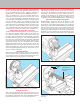
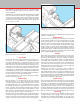
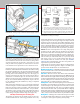
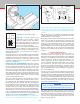
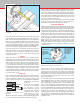
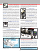
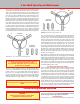
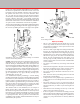
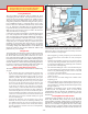
Table Of Contents
- Safety Rules for Power Tools
- An Introduction to the World of Miniature Machining
- Machine Terminology
- The Customer's Responsibility
- Learning More About Machining
- Visit the Sherline Website for the Latest Updates
- Lubrication
- Initial Assembly of a New Machine
- LATHE—Mounting the Crosslide
- All MILLS—X-Axis Handwheel Installation
- Digital Readout Handwheels
- 5000-Series Mills—Mounting the Column
- 2000- and 5800-Series Mills—Assembling and Mounting the Multi-Direction Column
- Mounting the Motor and Speed Control Unit to the Headstock
- Operation of the Motor and Electronic Speed Control
- What to Do if the Motor Suddenly Shuts Down
- Replacing Brushes on a DC Motor
- Mounting the Lathe or Mill to a Board for Stability
- Converting Machines from Inch to Metric and Vice Versa
- ADJUSTMENTS
- Two-Speed Pulley
- Spindle Preload Adjustment
- Gib Adjustment (Lathe and Mill)
- Backlash Adjustment (Lathe and Mill)
- Handwheel Adjustment (Lathe and Mill)
- Saddle Nut Adjustment (Lathe and Mill)
- Adjustment and Use of the Tailstock Gib
- Aligning the Headstock and Tailstock on the Lathe
- Squaring up Your Mill
- Use of Cutting Oils and Lubricants
- General Machining Terms
- Lathe Operating Instructions
- Digital Readouts, P/N 8200
- Live Center, P/N 1197
- Steady Rest, P/N 1074
- Thread Cutting Attachment, P/N 3100
- 3-Jaw, 4-Jaw and Drill Chucks
- Accessories for Your Lathe
- Guide to Approximate Turning Speeds
- Inserted Tip Carbide Tools
- Using the Cutoff or Parting Tool
- Tool Shapes and Grinding Your Own Cutting Tools
- Taper Turning
- Faceplate Turning
- Reaming
- Headstock Drilling
- Tailstock Drilling
- Center Drilling
- Removing Tools from the Morse Taper Spindles
- Turning Between Centers
- Holding the Workpiece
- Inducing Chatter and Learning How to Overcome It
- 3-Jaw Chuck Operation and Maintenance
- Vertical Milling Machine Operation
- Industrial Applications for Sherline Components
- Longer Tables and Taller Milling Columns Available
- Several Reasons to Consider CNC
- Learning About CNC
- CNC and CNC-Ready Sherline Lathes and Milling Machines
- CNC Rotary Indexer (P/N 8700)
- 4" Rotary Table (P/N 3700)
- Tilting Angle Table (P/N 3750)
- Mill Vise Set (P/N 3551)
- Drill Chucks (P/N 3072) and Center Drills
- Fly Cutters (P/N 3052 and P/N 7620)
- Boring Head (P/N 3054/3049)
- Mill Collet Set
- Drill Chuck Holder (P/N 3074)
- 3/8" End Mill Holder (P/N 3079)
- Accessories for Your Milling Machine
- Using the Mill Column Saddle Lock
- End Mills
- Cutting Speeds for Milling
- Determining the Depth of Cut
- Locating the Edge of a Part in Relation to the Spindle
- Using a Dial Indicator
- Standard Milling Versus Climb Milling
- Types of Milling Cutters
- Three Types of Work
- Purchasing Materials in Small Quantities
- Things to Consider Before You Start Cutting
- Locking the Axes
- Securing the Workpiece
- Helpful Tips for Milling
- General Description
- DRO Machine Operations
- Installing Stepper Motors
- Lead Wire Connection and Color Code
- Sherline Stepper Motor Specifications—Nmb Motors
- Using Handwheels on the Stepper Motors
- Stepper Motor Installation Instructions
- Sherline CNC Motor-Mounting Instructions
- Sherline Machine Technical Specifications

-21-
FIGURE 39—Long, shallow tapers can be cut in a continuous pass
by pivoting the headstock to the proper oset while supporting the
other end with the tailstock. The work is driven by using a drive
dog in the faceplate. The dog acts like a “universal joint” as the
drive pin slides in the faceplate slot. A dead center is used here
in the tailstock but an optional live center could also be used.
FIGURE 38—Turning a taper with the headstock slightly rotated.
must rst be removed. Loosen the set screw in the front of the
headstock, and lift the headstock and motor unit o the locating
pin. Tap the alignment key out of its slot on the bottom of the
headstock, and replace the headstock unit on the pin. While
pressing down on the headstock, rotate it to the angle you
desire by referring to the angle scale on the bed. The base is
calibrated in 5° increments up to 45° on either side of center.
When set to the proper angle, retighten the set screw against
the pin to lock the headstock into position. Tapers can also
be cut without turning the headstock by using a compound
slide (P/N 1270).
Short work can be inserted in a 3- or 4-jaw chuck and turned
as shown in Figure 38. If the headstock is angled towards the
lathe front, the taper will be cut smaller at the right. Tapered
holes can also be bored in work held in the 3- or 4- jaw chuck.
To machine a taper on longer stock, center drill both ends of
the bar, set the headstock angle and mount the part between
centers using a faceplate and drive dog. (See Figure 39.)
Tool Shapes and Grinding Your Own Cutting Tools
The shaping of cutting tools to suitable angles for the type
of material and nature of work being performed can be very
important to satisfactory work. When tools become dull, gently
re-grind and preserve the original angles and shapes. Do not
grind the top face of the tools, but conne sharpening to the
end and/or sides except form tools which are ground on the top
surface. Remember that heavy cuts and rapid feed will cause
greater strain on the chuck and lathe. This may induce “spring”
or binding of work and tools that can produce a poor nish.
NOTE: Because of the importance of a sharp and properly
ground tool to the cutting process, Sherline has prepared a
special instruction sheet on Grinding Your Own Lathe Tools.
There are a few tips that can make the process a simple one.
The instructions are included with each lathe and with cutting
tool sets when you order them from us, or you may call us
and request a copy. (Cost is $5.00 postage paid.) They are
also available from our website at no cost. (See sherline.
com/test-cuts/.) Unfortunately, space does not permit us to
reprint them as part of this booklet.
Cutting tools are ground to various shapes according to their
usage. Tools are usually ground to shape as needed by the
operator. Some standard tools are described below:
Normal Turning Tool—or RIGHT-hand tool feeds from right
to left, is used to reduce work to the desired diameter and is
the most frequently used of all tools.
Side Tools—These are used to face o the ends of shoulders
and may also be used as normal turning tools. Note that a tool
that is fed from left to right and has its cutting edge on the right
is called a LEFT-hand side tool because the chip comes o to
the left. Cutting tools are named based on which direction the
chip comes o, not which side has the cutting face.
Parting Tool—The conventional parting tool or cuto tool is
shaped like a dovetail when viewed from above and is used to
cut o work pieces by feeding the end of the tool across the
lathe bed and through the work piece. The Sherline parting
tool instead uses a thin .040" (1 mm) blade that has a slightly
thicker ridge at the top to accomplish the same job of providing
clearance for the tool while cutting. Parting tools thicker than
.040" (1 mm) will be too thick for use on your Sherline lathe.
Boring Tool—A boring tool is used in the tool post on a lathe
or in an o-settable boring head on a mill to enlarge holes in
a work piece. (See Figures 41 [lathe] and 58 [mill].)
FIGURE 40—Cutting tool shapes
NORMAL TURNING TOOLS (SIDE TOOLS)*
BORING TOOL*
THREADING TOOL**
INSIDE
THREADING TOOL
(P/N 1200)
PARTING TOOL***
* These shapes are available in high speed steel tool set, P/N 3007.
** The 60° threading tool is included as part of the carbide tool set, P/N
3006 and also comes with the thread cutting attachment (P/N 3100.)
*** The parting tool comes with the cuto tool holder, P/N 3002. Other
shapes are custom ground to accomplish special purposes as needed.
LEFT-HAND
RIGHT-HAND