
Sherline 4400 Lathes - Assembly and Instruction Guide
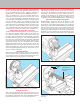
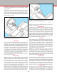
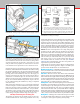
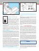
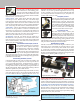
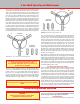
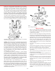
Table Of Contents
- Safety Rules for Power Tools
- An Introduction to the World of Miniature Machining
- Machine Terminology
- The Customer's Responsibility
- Learning More About Machining
- Visit the Sherline Website for the Latest Updates
- Lubrication
- Initial Assembly of a New Machine
- LATHE—Mounting the Crosslide
- All MILLS—X-Axis Handwheel Installation
- Digital Readout Handwheels
- 5000-Series Mills—Mounting the Column
- 2000- and 5800-Series Mills—Assembling and Mounting the Multi-Direction Column
- Mounting the Motor and Speed Control Unit to the Headstock
- Operation of the Motor and Electronic Speed Control
- What to Do if the Motor Suddenly Shuts Down
- Replacing Brushes on a DC Motor
- Mounting the Lathe or Mill to a Board for Stability
- Converting Machines from Inch to Metric and Vice Versa
- ADJUSTMENTS
- Two-Speed Pulley
- Spindle Preload Adjustment
- Gib Adjustment (Lathe and Mill)
- Backlash Adjustment (Lathe and Mill)
- Handwheel Adjustment (Lathe and Mill)
- Saddle Nut Adjustment (Lathe and Mill)
- Adjustment and Use of the Tailstock Gib
- Aligning the Headstock and Tailstock on the Lathe
- Squaring up Your Mill
- Use of Cutting Oils and Lubricants
- General Machining Terms
- Lathe Operating Instructions
- Digital Readouts, P/N 8200
- Live Center, P/N 1197
- Steady Rest, P/N 1074
- Thread Cutting Attachment, P/N 3100
- 3-Jaw, 4-Jaw and Drill Chucks
- Accessories for Your Lathe
- Guide to Approximate Turning Speeds
- Inserted Tip Carbide Tools
- Using the Cutoff or Parting Tool
- Tool Shapes and Grinding Your Own Cutting Tools
- Taper Turning
- Faceplate Turning
- Reaming
- Headstock Drilling
- Tailstock Drilling
- Center Drilling
- Removing Tools from the Morse Taper Spindles
- Turning Between Centers
- Holding the Workpiece
- Inducing Chatter and Learning How to Overcome It
- 3-Jaw Chuck Operation and Maintenance
- Vertical Milling Machine Operation
- Industrial Applications for Sherline Components
- Longer Tables and Taller Milling Columns Available
- Several Reasons to Consider CNC
- Learning About CNC
- CNC and CNC-Ready Sherline Lathes and Milling Machines
- CNC Rotary Indexer (P/N 8700)
- 4" Rotary Table (P/N 3700)
- Tilting Angle Table (P/N 3750)
- Mill Vise Set (P/N 3551)
- Drill Chucks (P/N 3072) and Center Drills
- Fly Cutters (P/N 3052 and P/N 7620)
- Boring Head (P/N 3054/3049)
- Mill Collet Set
- Drill Chuck Holder (P/N 3074)
- 3/8" End Mill Holder (P/N 3079)
- Accessories for Your Milling Machine
- Using the Mill Column Saddle Lock
- End Mills
- Cutting Speeds for Milling
- Determining the Depth of Cut
- Locating the Edge of a Part in Relation to the Spindle
- Using a Dial Indicator
- Standard Milling Versus Climb Milling
- Types of Milling Cutters
- Three Types of Work
- Purchasing Materials in Small Quantities
- Things to Consider Before You Start Cutting
- Locking the Axes
- Securing the Workpiece
- Helpful Tips for Milling
- General Description
- DRO Machine Operations
- Installing Stepper Motors
- Lead Wire Connection and Color Code
- Sherline Stepper Motor Specifications—Nmb Motors
- Using Handwheels on the Stepper Motors
- Stepper Motor Installation Instructions
- Sherline CNC Motor-Mounting Instructions
- Sherline Machine Technical Specifications

-20-
the headstock by lowering it onto a block of wood extending
to the table on the mill will keep from knocking the column
out of alignment.
TAILSTOCK—The tailstock spindle does not have a through
hole and a drawbolt is not used. It is equipped with a Morse
#0 taper, and accessories such as drill chucks and centers
can be removed by turning the handwheel counter-clockwise
until the back of the taper hits the inside of the spindle and
the accessory is ejected
Center Drilling
Because the work turns and the drill does not on a lathe, it is
necessary to use a center drill before a standard drill can be
used. Due to the exibility of a standard drill bit, it will tend
to wander on the surface of the rotating work, whereas a center
drill is designed to seek the center and begin drilling. The 60°
point of the center drill makes a properly shaped index hole
for the tip of a live or dead center. It also provides an accurate
starting point for a standard drill. Cutting oil is recommended
for all drilling operations. A center drill should be withdrawn,
cleared of chips and oiled several times during the drilling of
a hole to keep the small tip from breaking o.
For more information, see the chart of commonly available
center drill sizes on page 34.
Tailstock Drilling
Hold the work in a 3- or 4-jaw chuck. If the work is longer
than approximately 3" (76 mm), support the free end with
a steady rest. Seat the drill chuck’s #0 Morse arbor into the
tailstock spindle and secure a center drill in the chuck. Adjust
the tailstock to bring the center drill close to the work and
lock it in position. Turn the tailstock handwheel to bring the
center drill forward. After the hole is started with the center
drill, switch to a standard drill bit of the desired size to drill
the hole. (See page 34 for more on drilling holes.)
The easiest way to center drill the end of a round shaft that has
a diameter too large to be put through the spindle is to support
it with a steady rest (P/N 1074) while the end is being drilled.
If this isn’t possible, nd the center with a centering square,
FIGURE 36—Tailstock center drilling. The work turns while the
drill is held stationary in the tailstock.
FIGURE 37—Headstock drilling. The drill turns in the headstock
spindle while the work is held stationary.
prick punch a mark and center drill by hand. (See page 25 for
a photo of a steady rest.)
Headstock Drilling
The drill chuck comes tted with a #0 Morse arbor that ts
in the tailstock spindle. To use it in the headstock, you will
need to rst change to the #1 Morse arbor that is included
with your chuck. To change arbors, put the drill chuck key in
its hole to give you better purchase to grip the chuck while
using a wrench to remove the #0 arbor. Replace it with the
larger #1 arbor. Put the drill chuck in the headstock. Then put
the drawbolt with its washer through the spindle hole from
the other end of the headstock and tighten the drawbolt. DO
NOT OVERTIGHTEN! (See Figure 37.)
Reaming
Twist drills will generally not drill perfectly accurate sizes,
and very small boring tools are not satisfactory in deep holes
because of their exibility. Therefore, reaming is used for
holes requiring accuracy within .0005" (.013 mm). Reamers
are available in any standard size, but they are rather expensive
and are generally not purchased to do one-of-a-kind type work.
Use them only when a boring tool cannot be used because
of the depth or size of the hole. Because of their length, they
cannot always be used on a small lathe.
Reamers are used only to “clean up” a hole. To make an
accurate hole, the work is drilled approximately .010" (.25
mm) smaller than the reamer size. The work should be slowly
rotated and the reamer slowly fed into the hole while applying
plenty of cutting oil. The reamer should be frequently removed
and cleared of chips. Never rotate a reamer backwards in the
work as this can dull the cutting edges.
Faceplate Turning
The faceplate has three slots that allow work to be bolted to
its surface. Flat work can be screwed directly to the faceplate.
Extra holes can be drilled to suit odd shaped work unsuitable
for a chuck. If the work is mounted o-center, be sure to
counterbalance the faceplate and use very low RPM. Don’t
hesitate to drill holes in or modify the faceplate as needed to do
a particular job. That’s what they are for. They are inexpensive
and you can have several on hand modied for special jobs.
Taper Turning
On some lathes, a taper is cut by osetting the tailstock. On
the Sherline lathe, taper turning is done by removing the
headstock key and turning the headstock to any angle away
from dead center. To rotate the headstock, the alignment key