
Sherline 4400 Lathes - Assembly and Instruction Guide
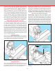
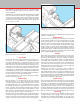
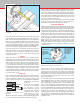
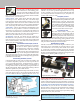
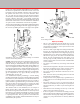
Table Of Contents
- Safety Rules for Power Tools
- An Introduction to the World of Miniature Machining
- Machine Terminology
- The Customer's Responsibility
- Learning More About Machining
- Visit the Sherline Website for the Latest Updates
- Lubrication
- Initial Assembly of a New Machine
- LATHE—Mounting the Crosslide
- All MILLS—X-Axis Handwheel Installation
- Digital Readout Handwheels
- 5000-Series Mills—Mounting the Column
- 2000- and 5800-Series Mills—Assembling and Mounting the Multi-Direction Column
- Mounting the Motor and Speed Control Unit to the Headstock
- Operation of the Motor and Electronic Speed Control
- What to Do if the Motor Suddenly Shuts Down
- Replacing Brushes on a DC Motor
- Mounting the Lathe or Mill to a Board for Stability
- Converting Machines from Inch to Metric and Vice Versa
- ADJUSTMENTS
- Two-Speed Pulley
- Spindle Preload Adjustment
- Gib Adjustment (Lathe and Mill)
- Backlash Adjustment (Lathe and Mill)
- Handwheel Adjustment (Lathe and Mill)
- Saddle Nut Adjustment (Lathe and Mill)
- Adjustment and Use of the Tailstock Gib
- Aligning the Headstock and Tailstock on the Lathe
- Squaring up Your Mill
- Use of Cutting Oils and Lubricants
- General Machining Terms
- Lathe Operating Instructions
- Digital Readouts, P/N 8200
- Live Center, P/N 1197
- Steady Rest, P/N 1074
- Thread Cutting Attachment, P/N 3100
- 3-Jaw, 4-Jaw and Drill Chucks
- Accessories for Your Lathe
- Guide to Approximate Turning Speeds
- Inserted Tip Carbide Tools
- Using the Cutoff or Parting Tool
- Tool Shapes and Grinding Your Own Cutting Tools
- Taper Turning
- Faceplate Turning
- Reaming
- Headstock Drilling
- Tailstock Drilling
- Center Drilling
- Removing Tools from the Morse Taper Spindles
- Turning Between Centers
- Holding the Workpiece
- Inducing Chatter and Learning How to Overcome It
- 3-Jaw Chuck Operation and Maintenance
- Vertical Milling Machine Operation
- Industrial Applications for Sherline Components
- Longer Tables and Taller Milling Columns Available
- Several Reasons to Consider CNC
- Learning About CNC
- CNC and CNC-Ready Sherline Lathes and Milling Machines
- CNC Rotary Indexer (P/N 8700)
- 4" Rotary Table (P/N 3700)
- Tilting Angle Table (P/N 3750)
- Mill Vise Set (P/N 3551)
- Drill Chucks (P/N 3072) and Center Drills
- Fly Cutters (P/N 3052 and P/N 7620)
- Boring Head (P/N 3054/3049)
- Mill Collet Set
- Drill Chuck Holder (P/N 3074)
- 3/8" End Mill Holder (P/N 3079)
- Accessories for Your Milling Machine
- Using the Mill Column Saddle Lock
- End Mills
- Cutting Speeds for Milling
- Determining the Depth of Cut
- Locating the Edge of a Part in Relation to the Spindle
- Using a Dial Indicator
- Standard Milling Versus Climb Milling
- Types of Milling Cutters
- Three Types of Work
- Purchasing Materials in Small Quantities
- Things to Consider Before You Start Cutting
- Locking the Axes
- Securing the Workpiece
- Helpful Tips for Milling
- General Description
- DRO Machine Operations
- Installing Stepper Motors
- Lead Wire Connection and Color Code
- Sherline Stepper Motor Specifications—Nmb Motors
- Using Handwheels on the Stepper Motors
- Stepper Motor Installation Instructions
- Sherline CNC Motor-Mounting Instructions
- Sherline Machine Technical Specifications

-19-
Inducing Chatter and Learning How to Overcome It
To better understand what is going on, we will now purposely
try to make the machine “chatter.” Make sure the stock you
are cutting is sticking out of the chuck no more than 1 inch
(25 mm). Crank the handwheel two turns further in from the
last setting which will give you a .100" (100 thousandths of an
inch) or 2 mm cut. Set the spindle speed to about 1000 RPM
(1/3 speed) and feed the tool slowly into the material. Vary
speed and feed until you get a substantial chatter. Without
changing the depth of the cut, drop the speed to about 200
RPM and feed the tool into the work with more force. The
chatter should disappear. Once you have learned to control
chatter by adjusting speed and feed, you will be well on your
way to becoming a machinist.
Holding the Workpiece
Work can be held between centers, in 3-jaw or 4-jaw chucks,
on the faceplate or with a collet. Sometimes it is necessary to
use a chuck and center, and, if the work is spinning fast, a live
center should be used. (See Figures 33, 34 and 35.)
would be similar to tearing an individual sheet of paper o
the roll. The results when cutting metal would be shorter tool
life, a poor nish and tool “chatter.” Chatter is a function of
rigidity, but it is controlled by speed (RPM) and feed rate.
Since you already have a piece of aluminum chucked up,
experiment with speed and feed rate. You just took a cut of
.010" (.25 mm) and probably noticed that the machine didn’t
even slow down in the slightest. Now take a 1/2 inch long cut
.050" or 1 mm deep, which is one complete revolution of the
handwheel. If you used the sharpened cutting tool that came
with your machine, it should have made the cut easily. If the
tool “squealed,” reduce the RPM a little and take another
.050" cut while feeding the tool faster. You will probably be
surprised at how easily your machine takes cuts this heavy.
Turning Between Centers
This is done by tting the dog to the work which is to be
turned and placing the work and dog between the centers in
the headstock and tailstock. The maximum diameter that can
be held with the dog is 5/8" (15 mm). (See Figure 35.)
FIGURE 33—Holding a round work piece in a 3-jaw chuck.
The dog is driven by tting it into one of the faceplate holes.
This method of turning is ideal for bar work or turning of
steps on a bar. The tailstock center must be greased to prevent
overheating. (An optional live center—such as P/N 1191—
turning on ball bearings is the solution preferred by most
machinists.) The headstock spindle has a #1 Morse taper in
the spindle nose. The tailstock spindle has a #0 Morse taper.
Removing Tools from the Morse Taper Spindles
HEADSTOCK—Accessories held in the Morse #1 taper
of the headstock spindle can be removed with the use of a
knockout bar (not supplied) approximately 3/8" in diameter
and 6" long. The bar is inserted through the back of the spindle,
and accessories, such as centers, can be removed with a few
taps. Accessories like the drill chuck that are drawn into the
spindle taper with a drawbolt are removed by loosening the
drawbolt a few turns and then giving the head of the bolt a
sharp tap with a mallet to break the taper loose. Supporting
FIGURE 34—Holding a square work piece in a 4-jaw chuck.
FIGURE 35—Turning between centers with a faceplate and
drive dog.
DOG
FACEPLATE
Grease tailstock center to
prevent overheating or use a
“Live center.”