
Sherline 4400 Lathes - Assembly and Instruction Guide
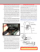
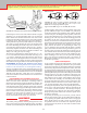
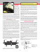
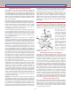
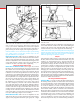
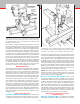
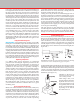
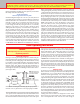
Table Of Contents
- Safety Rules for Power Tools
- An Introduction to the World of Miniature Machining
- Machine Terminology
- The Customer's Responsibility
- Learning More About Machining
- Visit the Sherline Website for the Latest Updates
- Lubrication
- Initial Assembly of a New Machine
- LATHE—Mounting the Crosslide
- All MILLS—X-Axis Handwheel Installation
- Digital Readout Handwheels
- 5000-Series Mills—Mounting the Column
- 2000- and 5800-Series Mills—Assembling and Mounting the Multi-Direction Column
- Mounting the Motor and Speed Control Unit to the Headstock
- Operation of the Motor and Electronic Speed Control
- What to Do if the Motor Suddenly Shuts Down
- Replacing Brushes on a DC Motor
- Mounting the Lathe or Mill to a Board for Stability
- Converting Machines from Inch to Metric and Vice Versa
- ADJUSTMENTS
- Two-Speed Pulley
- Spindle Preload Adjustment
- Gib Adjustment (Lathe and Mill)
- Backlash Adjustment (Lathe and Mill)
- Handwheel Adjustment (Lathe and Mill)
- Saddle Nut Adjustment (Lathe and Mill)
- Adjustment and Use of the Tailstock Gib
- Aligning the Headstock and Tailstock on the Lathe
- Squaring up Your Mill
- Use of Cutting Oils and Lubricants
- General Machining Terms
- Lathe Operating Instructions
- Digital Readouts, P/N 8200
- Live Center, P/N 1197
- Steady Rest, P/N 1074
- Thread Cutting Attachment, P/N 3100
- 3-Jaw, 4-Jaw and Drill Chucks
- Accessories for Your Lathe
- Guide to Approximate Turning Speeds
- Inserted Tip Carbide Tools
- Using the Cutoff or Parting Tool
- Tool Shapes and Grinding Your Own Cutting Tools
- Taper Turning
- Faceplate Turning
- Reaming
- Headstock Drilling
- Tailstock Drilling
- Center Drilling
- Removing Tools from the Morse Taper Spindles
- Turning Between Centers
- Holding the Workpiece
- Inducing Chatter and Learning How to Overcome It
- 3-Jaw Chuck Operation and Maintenance
- Vertical Milling Machine Operation
- Industrial Applications for Sherline Components
- Longer Tables and Taller Milling Columns Available
- Several Reasons to Consider CNC
- Learning About CNC
- CNC and CNC-Ready Sherline Lathes and Milling Machines
- CNC Rotary Indexer (P/N 8700)
- 4" Rotary Table (P/N 3700)
- Tilting Angle Table (P/N 3750)
- Mill Vise Set (P/N 3551)
- Drill Chucks (P/N 3072) and Center Drills
- Fly Cutters (P/N 3052 and P/N 7620)
- Boring Head (P/N 3054/3049)
- Mill Collet Set
- Drill Chuck Holder (P/N 3074)
- 3/8" End Mill Holder (P/N 3079)
- Accessories for Your Milling Machine
- Using the Mill Column Saddle Lock
- End Mills
- Cutting Speeds for Milling
- Determining the Depth of Cut
- Locating the Edge of a Part in Relation to the Spindle
- Using a Dial Indicator
- Standard Milling Versus Climb Milling
- Types of Milling Cutters
- Three Types of Work
- Purchasing Materials in Small Quantities
- Things to Consider Before You Start Cutting
- Locking the Axes
- Securing the Workpiece
- Helpful Tips for Milling
- General Description
- DRO Machine Operations
- Installing Stepper Motors
- Lead Wire Connection and Color Code
- Sherline Stepper Motor Specifications—Nmb Motors
- Using Handwheels on the Stepper Motors
- Stepper Motor Installation Instructions
- Sherline CNC Motor-Mounting Instructions
- Sherline Machine Technical Specifications

-18-
Lathe Operating Instructions
CAUTION!
Read All Operating Instructions Carefully Before Attempting
Any Machining Operations.
Leveling the Cutting Tool
Each type of turning work requires the correct tool for the job.
It is important that the cutting tool be sharp and correctly set up
in the tool post. The cutting edge of the tool should be exactly
level with the center height of the lathe. Check this by bringing
the tool tip up to the point of either the headstock center or
tailstock center. (See Figure 32A.) We also manufacture a
simple tool height adjustment gauge that allows you to check
tool height at any time by measuring from the table surface.
(See Figure 32B.)
FIGURE 32—Leveling the tool using (A) the tip of a head- or
tailstock center or (B) Sherline’s tool height gauge P/N 3009.
NOTE: Upper position is for
tools held in extended tool
post used with riser blocks.
HEIGHT Gauge
P/N 3009
CROSSLIDE
TOOL POST
CENTER
A
B
The standard Sherline tool post is designed to hold common
1/4" square tool bits which have had a few thousandths of an
inch (.1 mm) ground o the top edge for sharpening. Loosen
the hold-down bolt and slide the tool post as close to the point
of the dead center as possible. Inspect with a magnifying glass.
The tip of the tool bit may be raised or lowered by sliding a
shim* underneath it. The cutting edge must be on center or
just below center (0.004" or .01 mm maximum). Ensure that
the tool is xed securely in position by rmly tightening the
socket head screws. Try not to have the tool cutting edge
protruding more than 3/8" (10 mm) from the tool post.
*NOTE: Thin metal shim stock is available for this purpose.
If you don’t have any metal thin enough, a single thickness of
paper business card stock will usually do the job. Do not use
more than one thickness as it will compress too much. Our
optional rocker tool post (P/N 3057) allows this adjustment
to be made without shims. It comes standard with the Model
4400/4410 long bed lathe.
Initial Test Cutting
If you have never operated a lathe before, we suggest that you
make a trial cut on a scrap of material to learn the operation of
the machine. In a 3- or 4-jaw chuck, secure a piece of round
aluminum stock approximately 3/4" (19 mm) diameter and
1-1/2" (38 mm) long. Secure the pre-sharpened 1/4" square
right-hand cutting tool supplied with the lathe in the tool post,
making sure that it is properly positioned. First, turn the speed
control all the way counter-clockwise, then turn the motor
on. Bring the speed up to approximately 1000 RPM (about
1/3 speed). To establish tool position in relation to the work,
bring the tool in slowly until it just starts to scribe a line on
the work. Crank the tool towards the tailstock until it clears
the end of the work. Advance the tool .010" (.25 mm) using
the crosslide handwheel (10 divisions on the inch handwheel
scale). Using the bed handwheel, move the tool slowly across
the work toward the headstock.
Cutting tools used on lathes are designed to remove metal
much as paper is removed from a roll. It takes a positive feed
rate to accomplish this. If the feed rate isn’t fast enough, it
What is “Tool Chatter?” To see a video demonstration of what “chatter” actually sounds like and how to cure it, see
the Sherline website at sherline.com/test-cuts/. The page contains short video clips of various materials from Delrin to
Inconel being cut on a Sherline lathe. At the bottom of the page is a link to a video demonstration of chatter.
General Rules for Feed Rates and Cutting Speeds
Before attempting to machine any metal, please try to remember
this simple rule about machining:
“If the tool chatters,
decrease speed and increase feed.”
Understanding this simple rule can save you many hours of
grief. When the tool “chatters,” it is not cutting in a continuous
fashion. Metal likes to be machined in a way that allows the
material to come o in a continuous strip while the tool is
in contact with the metal. If the tool is not fed at a rate that
is fast enough, the tool skips along the surface, occasionally
digging in. The surface of the tool that is doing the most
cutting will nd a frequency of vibration that is a product of
all the variables involved. This can cause anything from a
high pitched whine on light, high speed cuts to a resonating
racket that can rip the work out of the chuck on heavy cuts.
If you maintain the same feed rate and reduce the RPM, the
feed will increase because the chip will be thicker. (If that
sounds wrong at rst, think of it this way: At the same feed
rate, if you cut the RPM in half, twice as much metal must be
removed with each rotation to get to the end of the cut in the
same amount of time. The chip is twice as thick, so the feed
is GREATER at lower RPM if the feed RATE stays constant.)
When a tool chatters, it gets dull faster, because it must keep
cutting through the previously machined surface that has been
“work hardened” by machining. As you can imagine, there are
limits to how much you can increase feed rate, so the answer
lies in adjusting both speed and feed to achieve the proper cut.
Proper cutting speed is the rate a particular material can be
machined without damaging the cutting edge of the tool that
is machining it. It is based on the surface speed of the material
in relation to the cutter. This speed is a function of both the
RPM of the spindle as well as the diameter of the part or
size of the cutter, because, as the part diameter or cutter size
increases, the surface moves a greater distance in a single
rotation. If you exceed this ideal speed, you can damage the
cutting tool. In the lathe and mill instructions, we give some
examples of suggested cutting speeds, but what we wanted
to get across here is that the damage isn’t a slow process. A
tool can be destroyed in just a few seconds. It isn’t a case of
getting only one hour of use instead of two. The cutting edge
actually melts. If you machine tough materials like stainless
steel, you will ruin more tools than you care to buy if you
don’t pay a lot of attention to cutting speeds. Charts showing
suggested cutting speeds for various materials are included
in both the lathe and mill sections that follow.