
Sherline 4400 Lathes - Assembly and Instruction Guide
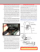
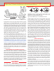
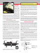
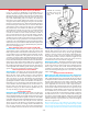
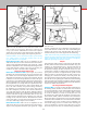
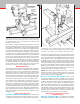
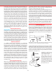
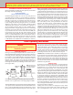
Table Of Contents
- Safety Rules for Power Tools
- An Introduction to the World of Miniature Machining
- Machine Terminology
- The Customer's Responsibility
- Learning More About Machining
- Visit the Sherline Website for the Latest Updates
- Lubrication
- Initial Assembly of a New Machine
- LATHE—Mounting the Crosslide
- All MILLS—X-Axis Handwheel Installation
- Digital Readout Handwheels
- 5000-Series Mills—Mounting the Column
- 2000- and 5800-Series Mills—Assembling and Mounting the Multi-Direction Column
- Mounting the Motor and Speed Control Unit to the Headstock
- Operation of the Motor and Electronic Speed Control
- What to Do if the Motor Suddenly Shuts Down
- Replacing Brushes on a DC Motor
- Mounting the Lathe or Mill to a Board for Stability
- Converting Machines from Inch to Metric and Vice Versa
- ADJUSTMENTS
- Two-Speed Pulley
- Spindle Preload Adjustment
- Gib Adjustment (Lathe and Mill)
- Backlash Adjustment (Lathe and Mill)
- Handwheel Adjustment (Lathe and Mill)
- Saddle Nut Adjustment (Lathe and Mill)
- Adjustment and Use of the Tailstock Gib
- Aligning the Headstock and Tailstock on the Lathe
- Squaring up Your Mill
- Use of Cutting Oils and Lubricants
- General Machining Terms
- Lathe Operating Instructions
- Digital Readouts, P/N 8200
- Live Center, P/N 1197
- Steady Rest, P/N 1074
- Thread Cutting Attachment, P/N 3100
- 3-Jaw, 4-Jaw and Drill Chucks
- Accessories for Your Lathe
- Guide to Approximate Turning Speeds
- Inserted Tip Carbide Tools
- Using the Cutoff or Parting Tool
- Tool Shapes and Grinding Your Own Cutting Tools
- Taper Turning
- Faceplate Turning
- Reaming
- Headstock Drilling
- Tailstock Drilling
- Center Drilling
- Removing Tools from the Morse Taper Spindles
- Turning Between Centers
- Holding the Workpiece
- Inducing Chatter and Learning How to Overcome It
- 3-Jaw Chuck Operation and Maintenance
- Vertical Milling Machine Operation
- Industrial Applications for Sherline Components
- Longer Tables and Taller Milling Columns Available
- Several Reasons to Consider CNC
- Learning About CNC
- CNC and CNC-Ready Sherline Lathes and Milling Machines
- CNC Rotary Indexer (P/N 8700)
- 4" Rotary Table (P/N 3700)
- Tilting Angle Table (P/N 3750)
- Mill Vise Set (P/N 3551)
- Drill Chucks (P/N 3072) and Center Drills
- Fly Cutters (P/N 3052 and P/N 7620)
- Boring Head (P/N 3054/3049)
- Mill Collet Set
- Drill Chuck Holder (P/N 3074)
- 3/8" End Mill Holder (P/N 3079)
- Accessories for Your Milling Machine
- Using the Mill Column Saddle Lock
- End Mills
- Cutting Speeds for Milling
- Determining the Depth of Cut
- Locating the Edge of a Part in Relation to the Spindle
- Using a Dial Indicator
- Standard Milling Versus Climb Milling
- Types of Milling Cutters
- Three Types of Work
- Purchasing Materials in Small Quantities
- Things to Consider Before You Start Cutting
- Locking the Axes
- Securing the Workpiece
- Helpful Tips for Milling
- General Description
- DRO Machine Operations
- Installing Stepper Motors
- Lead Wire Connection and Color Code
- Sherline Stepper Motor Specifications—Nmb Motors
- Using Handwheels on the Stepper Motors
- Stepper Motor Installation Instructions
- Sherline CNC Motor-Mounting Instructions
- Sherline Machine Technical Specifications

-17-
to the lower end of the Z-axis movement so that end mills can
be brought down below the surface of the table for working on
the edge of parts. This travel extension is now standard on all
Model 2000 mills. The headstock may be lowered even more
by placing the column top (P/N 56550) above the swing arm
instead of below it. Remove the ange nut, hold-down washer
and swing arm. Place the swing arm over the hold-down bolt
directly on top of the column base (P/N 56660). Place the
column top back onto the hold-down bolt upside down and
replace the hold-down washer and ange nut. Although you
cannot use the alignment lines to help square up the head, this
makes for a very strong and stable setup. In most cases the
new travel extension will make this procedure unnecessary.
Should you wish to work on extremely tall setups that combine
several holding devices (i.e., a chuck on top of a rotary table
on top of a tilting angle table) you can extend Z-axis travel
on the top end by either adding an additional spacer block to
the column or by removing the saddle travel extension and
attaching the saddle directly to the saddle nut as is done on
standard Sherline mills. This information also applies to the
5800-series mills.
Using the Saddle Locking Lever
All Sherline Mills—Along with the travel extension, a new saddle
locking lever was installed to replace the old saddle friction lock
used prior to 2/99. This new locking lever is standard on all
manual mills and vertical milling columns as of that date. This
lever is located on the Z-axis leadscrew behind the saddle. When
turned to the full clockwise position the saddle will move freely.
A spring-loaded ball locates in a detent in the bottom of the lever
to hold it in this position. To lock the saddle in position, move
the lever to the full counterclockwise position. This locks the
lever against the saddle nut which prevents the leadscrew from
turning. The exploded views on page 45 (manual) and page 46
(CNC) show the location of the components.
Engineering Compromises
It is dicult when writing instructions on complicated
procedures like describing the alignment procedure for this
mill. By giving you this much information we know that it
is making life easier for some customers by answering their
questions. On the other hand, it is probably confusing to
another customer who would never have asked the question,
because of the type of work that they perform on their mill or
lathe. We don’t want to create a customer who spends all his
time trying to achieve perfect alignment for work that doesn’t
require it and ends up never using the machine. Engineering
is always a compromise. We deal with this fact with each new
product that we design. While our machines aren’t accurate
enough for some customers, they are still too expensive for
others. We hope you are pleased with the new capabilities
this multi-direction mill can bring to your shop. We think
you will nd the combination of features oers a very good
machining value.
Use of Cutting Oils and Lubricants
Much can be written about the use of lubricants, but they may
usually be dispensed with where production rates are not very
important. A small amount of any kind of oil applied with a
small brush will be sucient. Aluminum and its alloys may
require the use of cutting oil to prevent the chips from welding
to the tool’s point. Do not use oils with a low ash point or
a bad smell. If desired, a mixture of one part soluble oil to
six parts water may be used on steel to assist in producing
CUT
CUT
FEED
FEED
A
B
a smoother nish and reduce tool chatter when parting o.
Brass and cast iron are always turned dry. Cutting lubricants
should be cleaned o the tools after use.
Cutting oils can be purchased at an industrial supply store. In
the past it was sold only in “industrial” quantities that were too
large for home shop use, however, several industrial suppliers
now sell it in quantities small enough to be practical for the
home machinist. Do not use high sulfur pipe thread cutting
oil. It is good for hard-to-machine materials, but is so dirty to
work with we do not recommend it. We also nd some of the
cutting uids used for tapping are too smelly and unpleasant
to use for general machining.
The main purpose of using lubricants is to keep the chips
from sticking to the cutting tool. When used properly, modern
high-speed tool bits are not likely to be aected by heat on
the type of work usually done on miniature machine tools.
General Machining Terms
Two terms frequently used in machining are “feed” and “cut.”
Reference to the diagrams that follow will show what is meant
by these terms. Normal turning on a lathe, when used to
reduce the diameter of a work piece, involves advancing the
cutting tool perpendicular to the lathe bed by an appropriate
amount (depth of cut) and feeding the tool along parallel to
the lathe bed to remove material over the desired length. (See
Figure 30A.)
FIGURE 30—Directions of Feed and Cut showing (A) Turning
work between centers and (B) Facing o a work piece
In normal lathe turning, the depth of cut is set by the crosslide
handwheel, and the feed is provided by the handwheel on the
end of the bed. When facing o the end of a work piece held in
a chuck or faceplate, the depth of cut is set by the handwheel
on the end of the bed, and the feed is provided by the crosslide
handwheel. (See Figure 31.)
FIGURE 31—Directions of
Feed and Cut when working
with a milling machine
When using a mill, cut is
determined by the amount of
depth the cutter is set to by
the Z-axis handwheel. Feed
is supplied by either or both
the X- or Y-axis handwheels
depending on the desired
direction of the cut.
CUT (Z-AXIS)
FEED (X-AXIS)
FEED (Y-AXIS)