
Sherline 4400 Lathes - Assembly and Instruction Guide
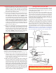
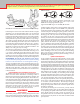
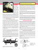
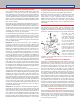
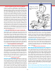
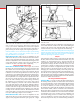
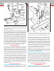
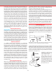
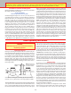
Table Of Contents
- Safety Rules for Power Tools
- An Introduction to the World of Miniature Machining
- Machine Terminology
- The Customer's Responsibility
- Learning More About Machining
- Visit the Sherline Website for the Latest Updates
- Lubrication
- Initial Assembly of a New Machine
- LATHE—Mounting the Crosslide
- All MILLS—X-Axis Handwheel Installation
- Digital Readout Handwheels
- 5000-Series Mills—Mounting the Column
- 2000- and 5800-Series Mills—Assembling and Mounting the Multi-Direction Column
- Mounting the Motor and Speed Control Unit to the Headstock
- Operation of the Motor and Electronic Speed Control
- What to Do if the Motor Suddenly Shuts Down
- Replacing Brushes on a DC Motor
- Mounting the Lathe or Mill to a Board for Stability
- Converting Machines from Inch to Metric and Vice Versa
- ADJUSTMENTS
- Two-Speed Pulley
- Spindle Preload Adjustment
- Gib Adjustment (Lathe and Mill)
- Backlash Adjustment (Lathe and Mill)
- Handwheel Adjustment (Lathe and Mill)
- Saddle Nut Adjustment (Lathe and Mill)
- Adjustment and Use of the Tailstock Gib
- Aligning the Headstock and Tailstock on the Lathe
- Squaring up Your Mill
- Use of Cutting Oils and Lubricants
- General Machining Terms
- Lathe Operating Instructions
- Digital Readouts, P/N 8200
- Live Center, P/N 1197
- Steady Rest, P/N 1074
- Thread Cutting Attachment, P/N 3100
- 3-Jaw, 4-Jaw and Drill Chucks
- Accessories for Your Lathe
- Guide to Approximate Turning Speeds
- Inserted Tip Carbide Tools
- Using the Cutoff or Parting Tool
- Tool Shapes and Grinding Your Own Cutting Tools
- Taper Turning
- Faceplate Turning
- Reaming
- Headstock Drilling
- Tailstock Drilling
- Center Drilling
- Removing Tools from the Morse Taper Spindles
- Turning Between Centers
- Holding the Workpiece
- Inducing Chatter and Learning How to Overcome It
- 3-Jaw Chuck Operation and Maintenance
- Vertical Milling Machine Operation
- Industrial Applications for Sherline Components
- Longer Tables and Taller Milling Columns Available
- Several Reasons to Consider CNC
- Learning About CNC
- CNC and CNC-Ready Sherline Lathes and Milling Machines
- CNC Rotary Indexer (P/N 8700)
- 4" Rotary Table (P/N 3700)
- Tilting Angle Table (P/N 3750)
- Mill Vise Set (P/N 3551)
- Drill Chucks (P/N 3072) and Center Drills
- Fly Cutters (P/N 3052 and P/N 7620)
- Boring Head (P/N 3054/3049)
- Mill Collet Set
- Drill Chuck Holder (P/N 3074)
- 3/8" End Mill Holder (P/N 3079)
- Accessories for Your Milling Machine
- Using the Mill Column Saddle Lock
- End Mills
- Cutting Speeds for Milling
- Determining the Depth of Cut
- Locating the Edge of a Part in Relation to the Spindle
- Using a Dial Indicator
- Standard Milling Versus Climb Milling
- Types of Milling Cutters
- Three Types of Work
- Purchasing Materials in Small Quantities
- Things to Consider Before You Start Cutting
- Locking the Axes
- Securing the Workpiece
- Helpful Tips for Milling
- General Description
- DRO Machine Operations
- Installing Stepper Motors
- Lead Wire Connection and Color Code
- Sherline Stepper Motor Specifications—Nmb Motors
- Using Handwheels on the Stepper Motors
- Stepper Motor Installation Instructions
- Sherline CNC Motor-Mounting Instructions
- Sherline Machine Technical Specifications

-16-
t as closely as possible. We have found the best way to deal
with this potential problem is to push the head square against
the key before tightening the cone point screw that locks the
headstock in place. If you ever want to check alignment of the
key to the column bed, mount a dial indicator in the spindle.
Raise and lower the head while reading the vertical edge of a
precision square. (See Figure 29.) Adjust the rotating column
until there is no error as the indicator moves up and down the
square. Now read the table with the indicator. If the slot and
key are perfect there shouldn’t be any error, but in most cases
there will be a small amount. This can usually be eliminated
by taking advantage of what play does exist in the alignment
key and slot. With the cone point set screw loosened slightly,
tap the headstock with a plastic mallet to take out play in the
direction you want to go. Then retighten the set screw.
Making Final Adjustments
The rotating column and tilting adjustments can be nalized
so the indicator needle shows no movement as the spindle is
rotated, however the error we measured when checking the
table atness could be accounted for now if need be. If the
pointer on the back of the rotary column disk doesn’t line up
with the zero mark, loosen the screw holding it in place and
reset it to indicate zero for future reference. (Model 2000 mills
and 5000-series mills with rotary column attachment only.)
Your machine is now “indicated in” and ready to use. As you
get a feel for your machine and go through this adjustment
procedure a few times, the time it takes to get good results
will decrease. Being able to accurately indicate in a mill is
one of the skills that must be developed by any machinist who
plans on making accurate parts. Though the adjustments on
larger machines may be made in slightly dierent ways, the
skills and procedures you learn here can be applied to other
machines as well.
Using the Column Spacer Block
Model 2000- and 5800-Series Mills (Standard)—In normal use the
column spacer block will not be required. However, if you are
working on a larger part or your setup requires more clearance
under the swing arm, the spacer block can be installed to raise
the column an additional two inches. (Installation will be made
easier if you rst remove the headstock/motor unit to reduce
the weight of the column.) To install the spacer block, remove
the ange nut on top of the column hold-down bolt, and lift
o the hold-down washer so that the entire column top and
swing arm assembly can be lifted o of the hold-down bolt.
Screw the extension bolt onto the end of the column bolt and
tighten with an adjustable wrench. Slide the column spacer
over the bolt and reinstall the column top and swing arm
assembly. Reinstall the headstock/motor unit.
NOTE: The column spacer block (P/N 56770 + 56110) is
included as standard with the Model 2000 mill. It is optional
at extra cost on all mill column upgrades and 8-direction
vertical milling columns and upgrades.
Model 5000- and 5400-Series Mills (Optional)—There is now
an optional column spacer block available for use with the
standard mill column. It is P/N 1300 and includes longer bolts
needed to attach the column to the base through the spacer
block. The spacer block will add 2" of additional distance
between the spindle and the table. If you simply need more
travel, there is also an optional 15" column bed (P/N 45260)
and matching leadscrew (P/N 45270/45280), allowing your
column to be converted from the standard 11" height to add
four more inches of Z-axis travel. This taller column can be
ordered as an extra cost option on all new mills.
Working with Setups that Require Extremely Low
or High Column Travel
Model 2000- and 5800-Series Mills—An upgrade to the Model
2000 mill was introduced in March, 1999. It adds 1.6" of travel
FIGURE 28—Squaring the fore and aft pivot movement of the
column with the Y-axis. (See the hint in the section on squaring
the X-axis above for a way to keep the tip of the indicator from
dropping into the T-slots.)
ADJUST FORE/AFT MOVEMENT
WITH CENTER ADJUSTMENT
SCREW ON ALIGNMENT BLOCK
LOCK ADJUSTMENT
IN PLACE WITH
11/16" FLANGE NUT
FIGURE 29—Fine tuning the headstock rotation alignment with
a machinist’s square and dial indicator. The headstock pivots
on the saddle pin. Even with the alignment key in place, slight
adjustment can be made to get the headstock perfectly square.
HEADSTOCK PIVOTS ON
SADDLE PIN. EVEN WITH
ALIGNMENT KEY IN PLACE,
SLIGHT ADJUSTMENT
CAN BE MADE TO GET
HEADSTOCK PERFECTLY
SQUARE.