
Sherline 4400 Lathes - Assembly and Instruction Guide
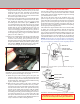
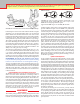
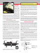
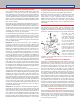
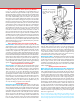
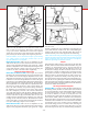
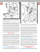
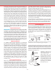
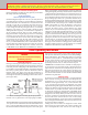
Table Of Contents
- Safety Rules for Power Tools
- An Introduction to the World of Miniature Machining
- Machine Terminology
- The Customer's Responsibility
- Learning More About Machining
- Visit the Sherline Website for the Latest Updates
- Lubrication
- Initial Assembly of a New Machine
- LATHE—Mounting the Crosslide
- All MILLS—X-Axis Handwheel Installation
- Digital Readout Handwheels
- 5000-Series Mills—Mounting the Column
- 2000- and 5800-Series Mills—Assembling and Mounting the Multi-Direction Column
- Mounting the Motor and Speed Control Unit to the Headstock
- Operation of the Motor and Electronic Speed Control
- What to Do if the Motor Suddenly Shuts Down
- Replacing Brushes on a DC Motor
- Mounting the Lathe or Mill to a Board for Stability
- Converting Machines from Inch to Metric and Vice Versa
- ADJUSTMENTS
- Two-Speed Pulley
- Spindle Preload Adjustment
- Gib Adjustment (Lathe and Mill)
- Backlash Adjustment (Lathe and Mill)
- Handwheel Adjustment (Lathe and Mill)
- Saddle Nut Adjustment (Lathe and Mill)
- Adjustment and Use of the Tailstock Gib
- Aligning the Headstock and Tailstock on the Lathe
- Squaring up Your Mill
- Use of Cutting Oils and Lubricants
- General Machining Terms
- Lathe Operating Instructions
- Digital Readouts, P/N 8200
- Live Center, P/N 1197
- Steady Rest, P/N 1074
- Thread Cutting Attachment, P/N 3100
- 3-Jaw, 4-Jaw and Drill Chucks
- Accessories for Your Lathe
- Guide to Approximate Turning Speeds
- Inserted Tip Carbide Tools
- Using the Cutoff or Parting Tool
- Tool Shapes and Grinding Your Own Cutting Tools
- Taper Turning
- Faceplate Turning
- Reaming
- Headstock Drilling
- Tailstock Drilling
- Center Drilling
- Removing Tools from the Morse Taper Spindles
- Turning Between Centers
- Holding the Workpiece
- Inducing Chatter and Learning How to Overcome It
- 3-Jaw Chuck Operation and Maintenance
- Vertical Milling Machine Operation
- Industrial Applications for Sherline Components
- Longer Tables and Taller Milling Columns Available
- Several Reasons to Consider CNC
- Learning About CNC
- CNC and CNC-Ready Sherline Lathes and Milling Machines
- CNC Rotary Indexer (P/N 8700)
- 4" Rotary Table (P/N 3700)
- Tilting Angle Table (P/N 3750)
- Mill Vise Set (P/N 3551)
- Drill Chucks (P/N 3072) and Center Drills
- Fly Cutters (P/N 3052 and P/N 7620)
- Boring Head (P/N 3054/3049)
- Mill Collet Set
- Drill Chuck Holder (P/N 3074)
- 3/8" End Mill Holder (P/N 3079)
- Accessories for Your Milling Machine
- Using the Mill Column Saddle Lock
- End Mills
- Cutting Speeds for Milling
- Determining the Depth of Cut
- Locating the Edge of a Part in Relation to the Spindle
- Using a Dial Indicator
- Standard Milling Versus Climb Milling
- Types of Milling Cutters
- Three Types of Work
- Purchasing Materials in Small Quantities
- Things to Consider Before You Start Cutting
- Locking the Axes
- Securing the Workpiece
- Helpful Tips for Milling
- General Description
- DRO Machine Operations
- Installing Stepper Motors
- Lead Wire Connection and Color Code
- Sherline Stepper Motor Specifications—Nmb Motors
- Using Handwheels on the Stepper Motors
- Stepper Motor Installation Instructions
- Sherline CNC Motor-Mounting Instructions
- Sherline Machine Technical Specifications

-15-
WHEN SQUARE,
SCRIBE ZERO
REFERENCE
MARK HERE
FIGURE 26—Squaring up the ram parallel to the Y-axis on the
2000-series mill. The indicator can be held with a chuck on the
table or a mill vise as shown here. When square, tighten the nut
on top of the column. 5000/5400-series mills can be adjusted
slightly by loosening the two bolts that hold the column base in
place, twisting the column slightly and retightening the bolts.
and the indicator is run around the surface of the bearing
race, which provides a round, at, parallel surface for the
tip of the indicator to run against.
Model 5000-Series Mills—This axis is not adjustable on the
5000-series mills, but it can be checked in the same manner.
Again, factory alignment should be quite good, but a slight
amount of adjustment can be obtained by loosening the four
screws that hold the column to the base and pressing the
column to one side or the other while retightening.
Squaring the Column with the Y-Axis
Model 2000- and 5800-Series Mills—(See Figure 28.) Loosen
the ange nut on the horizontal pivot pin just enough so that
the column can be moved using the adjustment screw in the
alignment block but there is no slop in the assembly. The tilt
is harder to set because the spindle doesn’t rotate at the pivot
point, but once you understand this, the task becomes simpler.
This is explained in the example that follows. The alignment
block adjustment screw helps make ne adjustments in this
direction easy. With the block in place and the ange nut
loose, the entire assembly is kept from falling forward by
the adjusting screw. This block can be left in place unless
the ram is completely retracted or the column is tilted back
at an angle that interferes with the block. With the indicator
still held in the spindle, take readings parallel with the Y-axis
near the front and rear edges of the table. Raise or lower the
column with the alignment block adjusting screw until the
readings are the same front and rear. Remember the location
of the pivot point as you take these measurements and allow
for it. (See following example in next column.)
Model 5000-Series Mills—This axis is not adjustable on the
5000-series mills, but it can be checked in the same manner.
Again, factory alignment should be quite good, but a slight
FIGURE 27—Squaring the left to right rotation of the column
with the X-axis.
amount of adjustment can be obtained by loosening the two
screws that hold the column to the base and shimming the
column at the front or back with thin metal shim stock* as
needed. Recheck your X-axis alignment after shimming.
*Hint: Shim stock can be purchased from most tooling supply
catalogs. If you don’t have metal shim stock available, cigarette
paper or business card stock can be used as a temporary
substitute depending on thickness needed.
Example:
If the indicator reading is larger at the front of the table than
the back, that means the column must be tilted back. Say your
reading is “0” at the back and .010" (.25 mm) at the front. If
you tipped the column back until the indicator read zero at
the front, the reading at the back would not remain at “0” but
would now be a negative reading. This is caused because the
pivot point is located far enough behind the spindle so that
both front and rear measuring points are still in front of it.
Swinging the column back actually raises both points. The
front point raises more than the back point, but both do go up.
You will have to keep tilting the column back and measuring
until you get the same reading front and back. This may require
more movement than you rst thought based on the dierence
between the initial measurements.
Fine Tuning the Headstock Alignment
All Sherline Mills—It is time to make the nal adjustments to
the rotating column, but rst we’ll add a little more confusion
to your life. Remember it was mentioned that alignment pins
are somewhat useless to line up a machine? Well, as much
as we hate to admit it, in a sense we already have one. It is
the alignment key that holds the headstock assembly square
to the column saddle, which is mounted on the column bed.
Removal of this key is what allows you to pivot the headstock
on Sherline lathes and mills. It is one of the features that make
our machines easy to use, versatile and very adaptable. It is
also another thing you have to consider when searching for
“perfect” alignment. If you have more than one key, try not
to mix them up because they are matched during assembly to