
Sherline 4400 Lathes - Assembly and Instruction Guide
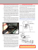
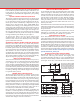
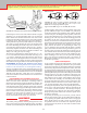
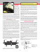
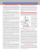
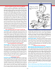
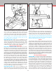
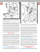
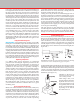
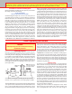
Table Of Contents
- Safety Rules for Power Tools
- An Introduction to the World of Miniature Machining
- Machine Terminology
- The Customer's Responsibility
- Learning More About Machining
- Visit the Sherline Website for the Latest Updates
- Lubrication
- Initial Assembly of a New Machine
- LATHE—Mounting the Crosslide
- All MILLS—X-Axis Handwheel Installation
- Digital Readout Handwheels
- 5000-Series Mills—Mounting the Column
- 2000- and 5800-Series Mills—Assembling and Mounting the Multi-Direction Column
- Mounting the Motor and Speed Control Unit to the Headstock
- Operation of the Motor and Electronic Speed Control
- What to Do if the Motor Suddenly Shuts Down
- Replacing Brushes on a DC Motor
- Mounting the Lathe or Mill to a Board for Stability
- Converting Machines from Inch to Metric and Vice Versa
- ADJUSTMENTS
- Two-Speed Pulley
- Spindle Preload Adjustment
- Gib Adjustment (Lathe and Mill)
- Backlash Adjustment (Lathe and Mill)
- Handwheel Adjustment (Lathe and Mill)
- Saddle Nut Adjustment (Lathe and Mill)
- Adjustment and Use of the Tailstock Gib
- Aligning the Headstock and Tailstock on the Lathe
- Squaring up Your Mill
- Use of Cutting Oils and Lubricants
- General Machining Terms
- Lathe Operating Instructions
- Digital Readouts, P/N 8200
- Live Center, P/N 1197
- Steady Rest, P/N 1074
- Thread Cutting Attachment, P/N 3100
- 3-Jaw, 4-Jaw and Drill Chucks
- Accessories for Your Lathe
- Guide to Approximate Turning Speeds
- Inserted Tip Carbide Tools
- Using the Cutoff or Parting Tool
- Tool Shapes and Grinding Your Own Cutting Tools
- Taper Turning
- Faceplate Turning
- Reaming
- Headstock Drilling
- Tailstock Drilling
- Center Drilling
- Removing Tools from the Morse Taper Spindles
- Turning Between Centers
- Holding the Workpiece
- Inducing Chatter and Learning How to Overcome It
- 3-Jaw Chuck Operation and Maintenance
- Vertical Milling Machine Operation
- Industrial Applications for Sherline Components
- Longer Tables and Taller Milling Columns Available
- Several Reasons to Consider CNC
- Learning About CNC
- CNC and CNC-Ready Sherline Lathes and Milling Machines
- CNC Rotary Indexer (P/N 8700)
- 4" Rotary Table (P/N 3700)
- Tilting Angle Table (P/N 3750)
- Mill Vise Set (P/N 3551)
- Drill Chucks (P/N 3072) and Center Drills
- Fly Cutters (P/N 3052 and P/N 7620)
- Boring Head (P/N 3054/3049)
- Mill Collet Set
- Drill Chuck Holder (P/N 3074)
- 3/8" End Mill Holder (P/N 3079)
- Accessories for Your Milling Machine
- Using the Mill Column Saddle Lock
- End Mills
- Cutting Speeds for Milling
- Determining the Depth of Cut
- Locating the Edge of a Part in Relation to the Spindle
- Using a Dial Indicator
- Standard Milling Versus Climb Milling
- Types of Milling Cutters
- Three Types of Work
- Purchasing Materials in Small Quantities
- Things to Consider Before You Start Cutting
- Locking the Axes
- Securing the Workpiece
- Helpful Tips for Milling
- General Description
- DRO Machine Operations
- Installing Stepper Motors
- Lead Wire Connection and Color Code
- Sherline Stepper Motor Specifications—Nmb Motors
- Using Handwheels on the Stepper Motors
- Stepper Motor Installation Instructions
- Sherline CNC Motor-Mounting Instructions
- Sherline Machine Technical Specifications

-14-
Why Aren’t Alignment Pins Used to Square up the Machine?
If you are a novice to machining, you probably believe a
machine should be designed so that a couple of pins could be
dropped into holes, squaring up the machine and eliminating
this whole alignment process. After all, that is the way they
do it with woodworking tools. The truth is the tolerances
that work well for wood cutting tools simply aren’t accurate
enough for most metalworking jobs. You just can’t hold the
tolerances required with “pins.” When they t tight enough to
lock the head square to the table you can’t remove them to do
work that isn’t square. They become more of a problem than
the problem they were installed to eliminate. For example,
an alignment or assembly error of .010" in a wooden kitchen
table will never be noticed. Usually the oor it sits on is not
even at. It would be a waste of time and eort to make it
more accurate than it has to be. On the other hand, a cylinder
that has been bored out of square with the crankshaft in an
automobile engine could wear the entire engine at an alarming
rate. The piston can go up and down over a million times in a
normal day’s use. The additional cost in fuel and shortened life
demands accuracy. Your Sherline mill should be adjusted and
aligned to the degree of accuracy demanded by the particular
job you are attempting to do.
Start by Getting the Column Close to Square with the Table
All Sherline Mills—The rst place to start is to get the column
approximately square with the table using the pointers and
laser engraved scales on the machine. The rst time you set it
up you will have to use a machinist’s square on the side-to-side
column rotary adjustment as the pointer will not have been
“zeroed in” yet. None of these adjustments must be extremely
precise at this point because a nger type dial indicator will be
used to make the nal adjustments later. Remove the headstock/
motor/speed control unit from the saddle. Place a machinist’s
square on the table and line up the front of the saddle to get
the column approximately square front to back. Then line up
on the right side of the saddle to get the column approximately
square side to side. Reinstall the headstock assembly.
Check for Any Built-in Error in Your Machine
All Sherline Mills—(See Figure 25.) To check the built-in error
of the machine use a dial indicator mounted in the spindle.
Move the table under spindle with the Y-axis handwheel
and note the error. This error will usually be around .001" to
.002" (.05 mm) in 3" (76 mm). (Remember, the components
are not precision ground, they are precision milled.) When
squaring the head later on this error should be accounted for.
Remember you are squaring the head and spindle to the base
of the machine where the saddle travels, not the surface of
the table itself. The head doesn’t have to be square for this
operation as long as you don’t rotate the spindle since you
are only checking for square in one direction.
Squaring up the Column
Model 2000- and 5800-Series Mills—(See Figure 26.) The next
decision to make is where the spindle is to be located. With
all the adjustments that can be made with the 8-direction mill
you’ll probably start with the spindle located near the middle
of the X/Y table movements. Something that isn’t too obvious
should be considered now. If the ram (the two-bar slide that
allows you to move the head in or out and left or right) isn’t
square with the X-axis, the rotating column calibrations will
have an error. To square up the ram, mount a dial indicator
to the worktable and move the X-axis back and forth while
reading the left and right surfaces of the column bed near the
bottom. This only has to be done if you will be rotating the
column and want to be able to rely on the angle graduation
readings. Once set, lock the ram in place with the ange nut.
Now you can scribe a line on the column base opposite the
“zero” mark for future reference as shown in Figure 25. We
can't engrave this mark at the factory. For perfect accuracy,
it must be done after each machine is aligned.
Model 5000-Series Mills—Though the column ram does not rotate
on the 5000-series mills, its squareness can still be checked
in the same manner if desired. The factory alignment of the
holes is quite accurate, but a small amount of adjustment is
available by loosening the two screws that hold the column
base to the bed and pressing the base to one side or the other
while retightening.
Squaring the Column with the X-Axis
Model 2000-Series Mills, Model 5800-Series Mills, OR 5000-Series
Mills with Optional Rotary Column Attachment—(See Figure 27.)
The column should next be squared with the X-axis. This is
accomplished with an indicator mounted in the spindle. Have
the four socket head cap screws used to clamp the column
rotation tight enough to keep the column from rotating, but
not so tight that you can’t move it with a light tap from a
plastic mallet to the column bed. Because the axis that allows
you to tilt the column in and out hasn’t been squared yet you
should only read the indicator at the same Y-axis location on
the worktable that you used before. Oset the indicator at
an angle in the spindle so that when the spindle is rotated it
describes about a 2" to 3" circle on the table. Take readings at
the extreme left and right positions. Adjust the column with
light taps until there is little dierence in the readings at either
extreme. Don’t try to get it perfect yet, just close enough so
there isn’t a gross error.
Hint: To keep the tip of the indicator from falling into the
T-slots, some machinists keep a large ball bearing on hand.
The two surfaces of a precision bearing are generally parallel.
The bearing is placed on the mill table centered on the spindle
WHEN SQUARE,
SCRIBE ZERO
REFERENCE
MARK HERE
FIGURE 25—Checking
for built in error in the
table travel along the
Y-axis