
Sherline 4400 Lathes - Assembly and Instruction Guide
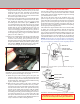
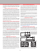
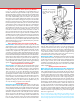
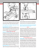
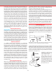
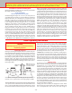
Table Of Contents
- Safety Rules for Power Tools
- An Introduction to the World of Miniature Machining
- Machine Terminology
- The Customer's Responsibility
- Learning More About Machining
- Visit the Sherline Website for the Latest Updates
- Lubrication
- Initial Assembly of a New Machine
- LATHE—Mounting the Crosslide
- All MILLS—X-Axis Handwheel Installation
- Digital Readout Handwheels
- 5000-Series Mills—Mounting the Column
- 2000- and 5800-Series Mills—Assembling and Mounting the Multi-Direction Column
- Mounting the Motor and Speed Control Unit to the Headstock
- Operation of the Motor and Electronic Speed Control
- What to Do if the Motor Suddenly Shuts Down
- Replacing Brushes on a DC Motor
- Mounting the Lathe or Mill to a Board for Stability
- Converting Machines from Inch to Metric and Vice Versa
- ADJUSTMENTS
- Two-Speed Pulley
- Spindle Preload Adjustment
- Gib Adjustment (Lathe and Mill)
- Backlash Adjustment (Lathe and Mill)
- Handwheel Adjustment (Lathe and Mill)
- Saddle Nut Adjustment (Lathe and Mill)
- Adjustment and Use of the Tailstock Gib
- Aligning the Headstock and Tailstock on the Lathe
- Squaring up Your Mill
- Use of Cutting Oils and Lubricants
- General Machining Terms
- Lathe Operating Instructions
- Digital Readouts, P/N 8200
- Live Center, P/N 1197
- Steady Rest, P/N 1074
- Thread Cutting Attachment, P/N 3100
- 3-Jaw, 4-Jaw and Drill Chucks
- Accessories for Your Lathe
- Guide to Approximate Turning Speeds
- Inserted Tip Carbide Tools
- Using the Cutoff or Parting Tool
- Tool Shapes and Grinding Your Own Cutting Tools
- Taper Turning
- Faceplate Turning
- Reaming
- Headstock Drilling
- Tailstock Drilling
- Center Drilling
- Removing Tools from the Morse Taper Spindles
- Turning Between Centers
- Holding the Workpiece
- Inducing Chatter and Learning How to Overcome It
- 3-Jaw Chuck Operation and Maintenance
- Vertical Milling Machine Operation
- Industrial Applications for Sherline Components
- Longer Tables and Taller Milling Columns Available
- Several Reasons to Consider CNC
- Learning About CNC
- CNC and CNC-Ready Sherline Lathes and Milling Machines
- CNC Rotary Indexer (P/N 8700)
- 4" Rotary Table (P/N 3700)
- Tilting Angle Table (P/N 3750)
- Mill Vise Set (P/N 3551)
- Drill Chucks (P/N 3072) and Center Drills
- Fly Cutters (P/N 3052 and P/N 7620)
- Boring Head (P/N 3054/3049)
- Mill Collet Set
- Drill Chuck Holder (P/N 3074)
- 3/8" End Mill Holder (P/N 3079)
- Accessories for Your Milling Machine
- Using the Mill Column Saddle Lock
- End Mills
- Cutting Speeds for Milling
- Determining the Depth of Cut
- Locating the Edge of a Part in Relation to the Spindle
- Using a Dial Indicator
- Standard Milling Versus Climb Milling
- Types of Milling Cutters
- Three Types of Work
- Purchasing Materials in Small Quantities
- Things to Consider Before You Start Cutting
- Locking the Axes
- Securing the Workpiece
- Helpful Tips for Milling
- General Description
- DRO Machine Operations
- Installing Stepper Motors
- Lead Wire Connection and Color Code
- Sherline Stepper Motor Specifications—Nmb Motors
- Using Handwheels on the Stepper Motors
- Stepper Motor Installation Instructions
- Sherline CNC Motor-Mounting Instructions
- Sherline Machine Technical Specifications

-12-
ADJUSTMENT SCREWS
TAILSTOCK CASE
ADJUSTMENT LOCKING
SET SCREWS
LOCKING SCREW
BRASS GIB
FIGURE 21—Adjusting the gibs
GIB LOCK
GIB
BED
SADDLE
FIGURE 23—
Components of the
tailstock case and
adjustable gib.
Gib Adjustment
(Lathe and Mill)
(See Figure 21)
Tapered gibs are
fitted to the mill
headstock, saddle
and table and to
the lathe saddle and
crosslide. Correct
adjustment of the
gibs will ensure
smooth and steady
operation of the
slides. The gib is
eectively a taper with an angle corresponding to the one
machined into the saddle. It is held in place by an “L” wire
gib lock that is secured with a locking screw. It is adjusted by
loosening the gib locking screw and pushing the tapered gib
inward until “play” is removed. After adjusting, retighten the
locking screw. Milling operations require a tighter adjustment
of the gibs than lathe operations.
Backlash Adjustment (Lathe and Mill)
Backlash is the amount the handwheel can be turned before
the slide starts to move when changing directions. This is a
fact of life on any machine tool, and on machines of this type
it should be about .003" to .005" (.08 mm to .12 mm).
Backlash must be allowed for by feeding in one direction only.
Example: You are turning a bar to .600" diameter. The bar
now measures .622" which requires a cut of .011" to bring it
to a nished diameter of .600". If the user inadvertently turns
the handwheel .012" instead of .011", he couldn’t reverse
the handwheel just .001" to correct the error. The handwheel
would have to be reversed for an amount greater than the
backlash in the feed screw before resetting the handwheel to
its proper position.
Backlash on the X- and Y-axes of the mill may be reduced to
a minimum by adjustment on the anti-backlash nuts. These
nuts are located on the handwheel ends of the mill saddle. The
nuts are secured by button head screws that hold a star gear
that interlocks with teeth on the nut.
To adjust backlash, simply loosen the button head screw that
locks the star gear. Rotate the anti-backlash nut clockwise
on the X-axis or counter-clockwise on the Y-axis until snug.
Retighten the button head screw while pushing the gear toward
the nut. With the anti-backlash nuts properly adjusted, the
leadscrews should turn smoothly and have no more than the
proper .003" to .005" of backlash.
Want to see some projects built by other Sherline
machinists? Visit sherline.com/workshop/.
LEADSCREW
SADDLE
SET SCREW
NUT
ANTI-
BACKLASH
NUT
FIGURE 22—Mill Backlash Adjustment
NOTE: Older mills use a “pointer” type lock instead of the star gear.
Handwheel Adjustment (Lathe and Mill)
The handwheels are secured to their corresponding leadscrew
shafts by a small set screw in the side of the handwheel base.
Check them periodically to make sure they have not been
loosened by vibration. On the adjustable “zero” handwheels,
you must rst release the rotating collar by loosening the
locking wheel. Then rotate the collar until you can see the
set screw through the small hole in the side of the collar and
adjust the screw as necessary.
If a handwheel has been removed, when reinstalling it, make
sure it is pushed up tightly against its thrust collar before
tightening the set screw. Push the appropriate table or saddle
toward the handwheel to remove any excess play before
tightening. For the mill Z-axis, lift up on the headstock to
remove play.
If excessive backlash develops at the handwheel and thrust
collar junctions, adjust by rst loosening the handwheel set
screw. Index (rotate) the handwheel so the set screw tightens on
a dierent part of the shaft. (If you don’t, it may tend to keep
picking up the previous tightening indentation and returning
to the same spot.) Push the handwheel in tightly while holding
the saddle and retighten the handwheel set screw.
Saddle Nut Adjustment (Lathe and Mill)
Both the lathe saddle and mill column saddle are connected
to their respective leadscrews using a similar brass saddle nut
(P/N 40170/41170 or 40177/41177). The saddle should rst be
positioned at the end of its travel as close to the handwheel as
possible. A socket head cap screw attaches the saddle nut to
the saddle, while two set screws align the nut to the leadscrew.
Loosen the cap screw, bring each set screw into light contact
with the saddle nut and retighten the cap screw. If binding
occurs, readjust the set screws.
NOTE: The mill column saddle nut diers from the lathe
leadscrew saddle nut in that it includes a spring-loaded ball
that engages a detent in the saddle locking lever. See pages
17, 32 and 33 for details on use of the saddle locking lever.
Adjustment and Use of the Tailstock Gib
The brass tailstock gib should be adjusted so that it is equally
tight at both ends and slides easily on the bed dovetail when
the adjustment screw is loosened. As the brass gib wears,
any play that develops can be adjusted out by loosening the
two set screws, readjusting the two button head screws and
then re-locking the set screws. To lock the tailstock in place
on the bed, tighten the center socket head cap screw. Do not
overtighten.
(NOTE: Lathes made prior to 1999 do not have a tailstock gib
adjustment. They are locked by means of a horizontal screw
through a split in the tailstock case.)