
Sherline 4400 Lathes - Assembly and Instruction Guide
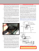
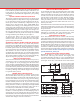
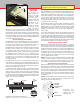
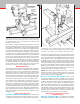
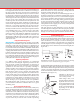
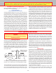
Table Of Contents
- Safety Rules for Power Tools
- An Introduction to the World of Miniature Machining
- Machine Terminology
- The Customer's Responsibility
- Learning More About Machining
- Visit the Sherline Website for the Latest Updates
- Lubrication
- Initial Assembly of a New Machine
- LATHE—Mounting the Crosslide
- All MILLS—X-Axis Handwheel Installation
- Digital Readout Handwheels
- 5000-Series Mills—Mounting the Column
- 2000- and 5800-Series Mills—Assembling and Mounting the Multi-Direction Column
- Mounting the Motor and Speed Control Unit to the Headstock
- Operation of the Motor and Electronic Speed Control
- What to Do if the Motor Suddenly Shuts Down
- Replacing Brushes on a DC Motor
- Mounting the Lathe or Mill to a Board for Stability
- Converting Machines from Inch to Metric and Vice Versa
- ADJUSTMENTS
- Two-Speed Pulley
- Spindle Preload Adjustment
- Gib Adjustment (Lathe and Mill)
- Backlash Adjustment (Lathe and Mill)
- Handwheel Adjustment (Lathe and Mill)
- Saddle Nut Adjustment (Lathe and Mill)
- Adjustment and Use of the Tailstock Gib
- Aligning the Headstock and Tailstock on the Lathe
- Squaring up Your Mill
- Use of Cutting Oils and Lubricants
- General Machining Terms
- Lathe Operating Instructions
- Digital Readouts, P/N 8200
- Live Center, P/N 1197
- Steady Rest, P/N 1074
- Thread Cutting Attachment, P/N 3100
- 3-Jaw, 4-Jaw and Drill Chucks
- Accessories for Your Lathe
- Guide to Approximate Turning Speeds
- Inserted Tip Carbide Tools
- Using the Cutoff or Parting Tool
- Tool Shapes and Grinding Your Own Cutting Tools
- Taper Turning
- Faceplate Turning
- Reaming
- Headstock Drilling
- Tailstock Drilling
- Center Drilling
- Removing Tools from the Morse Taper Spindles
- Turning Between Centers
- Holding the Workpiece
- Inducing Chatter and Learning How to Overcome It
- 3-Jaw Chuck Operation and Maintenance
- Vertical Milling Machine Operation
- Industrial Applications for Sherline Components
- Longer Tables and Taller Milling Columns Available
- Several Reasons to Consider CNC
- Learning About CNC
- CNC and CNC-Ready Sherline Lathes and Milling Machines
- CNC Rotary Indexer (P/N 8700)
- 4" Rotary Table (P/N 3700)
- Tilting Angle Table (P/N 3750)
- Mill Vise Set (P/N 3551)
- Drill Chucks (P/N 3072) and Center Drills
- Fly Cutters (P/N 3052 and P/N 7620)
- Boring Head (P/N 3054/3049)
- Mill Collet Set
- Drill Chuck Holder (P/N 3074)
- 3/8" End Mill Holder (P/N 3079)
- Accessories for Your Milling Machine
- Using the Mill Column Saddle Lock
- End Mills
- Cutting Speeds for Milling
- Determining the Depth of Cut
- Locating the Edge of a Part in Relation to the Spindle
- Using a Dial Indicator
- Standard Milling Versus Climb Milling
- Types of Milling Cutters
- Three Types of Work
- Purchasing Materials in Small Quantities
- Things to Consider Before You Start Cutting
- Locking the Axes
- Securing the Workpiece
- Helpful Tips for Milling
- General Description
- DRO Machine Operations
- Installing Stepper Motors
- Lead Wire Connection and Color Code
- Sherline Stepper Motor Specifications—Nmb Motors
- Using Handwheels on the Stepper Motors
- Stepper Motor Installation Instructions
- Sherline CNC Motor-Mounting Instructions
- Sherline Machine Technical Specifications

-10-
Removing the headstock alignment key permits the headstock
to be mounted in positions other than square. This allows you
to mill parts at an angle or turn tapers on the lathe. When
using the lathe or mill without the alignment key, keep cutting
loads light.
Operation of the Motor and Electronic Speed Control
The motor is supplied with current from an electronic speed
control that produces a comprehensive range of speeds suitable
for all operations. Special circuitry designed into the DC
motor speed control automatically compensates for speed
changes due to increased load. If the spindle RPM drops
noticeably when cutting, you are taking too heavy a cut. The
speed range of the spindle using the speed control is from 70
to 2800 RPM in the normal belt position. This is achieved
without the inconvenience of belt or gear ratio changes as is
the case with other designs. A second belt position is oered
as an additional feature to provide extra torque at low RPM
for larger diameter parts should your job require it.
To operate the motor, turn the speed control knob
counterclockwise as far as it will go Then turn the toggle
switch to “ON” and select the desired speed by turning the
speed control knob clockwise.
The Advantages of Sherline's DC Motor and Electronic Speed Control
Sherline’s 90-volt DC motor is very smooth and powerful,
particularly at low RPM. The specially designed electronics
package also provides some unique advantages in addition
to smooth speed control and a broad speed range. A special
circuit compensates for load, helping to keep RPM constant.
The machines can also be used on any electrical current
worldwide from 100 to 240 VAC, 50 or 60 Hz without further
adjustment other than seeing that the proper wall plug is used.
The control reads the incoming AC current and automatically
adjusts to output the proper DC current to the motor.
Motors are Pretested at the Factory
Your new motor should run smoothly the rst time you use it,
as it has been “run in” for about an hour before being shipped
to you. Despite our secure packaging, there have been cases
where extremely rough handling by a shipper has damaged the
magnets in the motor. If the motor does not run when plugged
in, turn the motor by hand. If it does not turn smoothly, it may
have been damaged in shipment. Call Sherline for instructions
on making a damage claim with the shipper. Do not attempt
to repair the motor yourself.
CAUTION—Motor is Thermally Protected
Thermal protection means there is a built-in circuit breaker
that will shut o the motor if it gets too hot. This keeps the
motor from burning out. The breaker will automatically reset
as soon as the motor cools, and you can go back to cutting,
but you should be aware of how it works and what to do if the
machine suddenly shuts itself o. If your motor is shutting
down from overheating on a regular basis, it means you are
taking cuts that are too heavy or operating at too high an RPM
for long periods. Slow your speed down, reduce your cut or
feed rate, and you should have no further problems.
Due to the nature of miniature machining, overloading the
machine is a common problem. It is often tempting to try to
speed up the process by working faster. Keep in mind this is a
small machine, and work with patience and precision—don’t
be in a hurry. Your parts will come out better, and your machine
will last much longer if it is not overstressed.
What to Do if the Motor Suddenly Shuts Down
If your thermal protection circuit shuts down the motor while
work is in progress, immediately shut o the power switch
and then back the tool out of the work. It should only take 10
seconds or less for the circuit breaker to reset. Then you can
turn the motor on and start the cut again, this time putting a
little less stress on the motor. If you leave the tool engaged
in the part and the power on, when the circuit breaker kicks
back on, the motor must start under load. This can be very
hard on your motor.
Remember that the circuit breaker turns the speed control o,
which turns o the motor. If power were to be applied to the
speed control with the motor disconnected, it could damage
the speed control.
Thermal protection is built into your motor to insure it is not
damaged by overloading. Use good common sense when
operating the motor for years of trouble-free operation.
Replacing Brushes on a DC Motor
Since 2002, Sherline has used DC motors with externally
replaceable brushes. The brushes are removed by using a large,
at-bladed screwdriver to unscrew the brush covers which are
located in round bosses on the sides of the motor near the rear.
New brushes and springs are inserted and the covers replaced.
Brushes should be replaced if they are chipped, worn unevenly
or if they are less than 1/4" long. DC motors supplied before
2002 utilize a dierent brush replacement procedure. If you
have the older style internal brushes, instructions for changing
them can be found at sherline.com/Wordpress/wp-content/
uploads/2016/01/dc_brush.pdf.
Mounting the Lathe or Mill to a Board for Stability
Mounting the lathe to a board is necessary because of the
narrow base. This keeps the machine from tipping. We
recommend mounting the lathe on a piece of nished shelf
material, which is readily available at most hardware stores.
(See Figure 18 for sizes.) The machine can be secured to the
FIGURE 18—Plans for mounting board hole patterns. Conrm
actual dimensions from your lathe or mill before drilling.
2.38"
2.25"
2.25"
2.38"
1.75"
16.5"
(5800-Series Mills)
12.5"
(2000-Series Mills)
10.5"
(5400-Series Mills)
8.5"
(5000-Series Mills)
2.38"
12" x 10" BASE20" x 12" BASE
36" x 10" BASE
24" x 10" BASE
7.19" 5.0"
2.25"
2.25"
.75" (5400)
1.5" (5000)
17.0" 3.5"
2.38"
4000/4100
LATHE
4400/4410
LATHE
FRONT
The overall sizes are based on standard
laminated shelf material. You may adjust
them to fit the material available to you.
The mill mounting boards will have to
be cut to length as shelf material is not
normally available in lengths that short.