
Sherline 4400 Lathes - Assembly and Instruction Guide
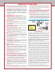
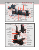
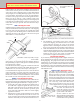
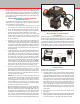
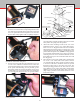
Table Of Contents
- Safety Rules for Power Tools
- An Introduction to the World of Miniature Machining
- Machine Terminology
- The Customer's Responsibility
- Learning More About Machining
- Visit the Sherline Website for the Latest Updates
- Lubrication
- Initial Assembly of a New Machine
- LATHE—Mounting the Crosslide
- All MILLS—X-Axis Handwheel Installation
- Digital Readout Handwheels
- 5000-Series Mills—Mounting the Column
- 2000- and 5800-Series Mills—Assembling and Mounting the Multi-Direction Column
- Mounting the Motor and Speed Control Unit to the Headstock
- Operation of the Motor and Electronic Speed Control
- What to Do if the Motor Suddenly Shuts Down
- Replacing Brushes on a DC Motor
- Mounting the Lathe or Mill to a Board for Stability
- Converting Machines from Inch to Metric and Vice Versa
- ADJUSTMENTS
- Two-Speed Pulley
- Spindle Preload Adjustment
- Gib Adjustment (Lathe and Mill)
- Backlash Adjustment (Lathe and Mill)
- Handwheel Adjustment (Lathe and Mill)
- Saddle Nut Adjustment (Lathe and Mill)
- Adjustment and Use of the Tailstock Gib
- Aligning the Headstock and Tailstock on the Lathe
- Squaring up Your Mill
- Use of Cutting Oils and Lubricants
- General Machining Terms
- Lathe Operating Instructions
- Digital Readouts, P/N 8200
- Live Center, P/N 1197
- Steady Rest, P/N 1074
- Thread Cutting Attachment, P/N 3100
- 3-Jaw, 4-Jaw and Drill Chucks
- Accessories for Your Lathe
- Guide to Approximate Turning Speeds
- Inserted Tip Carbide Tools
- Using the Cutoff or Parting Tool
- Tool Shapes and Grinding Your Own Cutting Tools
- Taper Turning
- Faceplate Turning
- Reaming
- Headstock Drilling
- Tailstock Drilling
- Center Drilling
- Removing Tools from the Morse Taper Spindles
- Turning Between Centers
- Holding the Workpiece
- Inducing Chatter and Learning How to Overcome It
- 3-Jaw Chuck Operation and Maintenance
- Vertical Milling Machine Operation
- Industrial Applications for Sherline Components
- Longer Tables and Taller Milling Columns Available
- Several Reasons to Consider CNC
- Learning About CNC
- CNC and CNC-Ready Sherline Lathes and Milling Machines
- CNC Rotary Indexer (P/N 8700)
- 4" Rotary Table (P/N 3700)
- Tilting Angle Table (P/N 3750)
- Mill Vise Set (P/N 3551)
- Drill Chucks (P/N 3072) and Center Drills
- Fly Cutters (P/N 3052 and P/N 7620)
- Boring Head (P/N 3054/3049)
- Mill Collet Set
- Drill Chuck Holder (P/N 3074)
- 3/8" End Mill Holder (P/N 3079)
- Accessories for Your Milling Machine
- Using the Mill Column Saddle Lock
- End Mills
- Cutting Speeds for Milling
- Determining the Depth of Cut
- Locating the Edge of a Part in Relation to the Spindle
- Using a Dial Indicator
- Standard Milling Versus Climb Milling
- Types of Milling Cutters
- Three Types of Work
- Purchasing Materials in Small Quantities
- Things to Consider Before You Start Cutting
- Locking the Axes
- Securing the Workpiece
- Helpful Tips for Milling
- General Description
- DRO Machine Operations
- Installing Stepper Motors
- Lead Wire Connection and Color Code
- Sherline Stepper Motor Specifications—Nmb Motors
- Using Handwheels on the Stepper Motors
- Stepper Motor Installation Instructions
- Sherline CNC Motor-Mounting Instructions
- Sherline Machine Technical Specifications

-8-
FIGURE 13—DC motor and speed control assembly.
Press the two nuts into the hex shaped depressions in the
rear of the inner belt guard and secure the outer cover with
two 1-3/8" pan head screws through the covers and into
the nuts. Don’t fully tighten until everything is aligned.
FIGURE 11—Attach outer belt guard.
4. On top of one end of the two belt guard halves you will
see two “ears” with holes in them. These are where the
speed control housing pivots. On the plate on the bottom
of the speed control housing are two pins that go into
these holes. Put the pin closest to the motor in place, then
bend the other “ear” away from the motor far enough that
you can engage the other pin so the cover pivots on these
FIGURE 12—Insert “ears” of speed control housing into holes
in belt guard tabs.
pins. The plastic is exible enough so that you can do this
easily and it will spring back into position.
5. Attach the motor mounting bracket to the rear of the
headstock with two 10-32 x 7/16" socket head screws.
These screws are shipped threaded into the headstock
rather than in the parts bag. There is enough “play” in the
mounting holes to allow the motor to be adjusted so it is
parallel with the spindle axis. (NOTE: If a chip guard is
to be mounted, its attachment screw replaces one of these
mounting screws. It can be mounted at this time or after
the headstock is in place. See instructions that come with
the chip guard.)
6. Place the drive belt over the spindle pulley and insert the
two 10-32 x 3/4" socket head screws (with 2 washers
on each) through the motor mount slot and into holes
in the ends of the motor standos which are exposed
through locating holes in the outer belt guard. The
normal operating position for the drive belt is on the
large diameter groove on the motor pulley and the small
diameter groove on the spindle pulley. Use of the other
(high torque) position is discussed elsewhere in the
instruction manual.
FIGURE 14—Attach motor to motor bracket.
FIGURE 10—Place belt over motor pulley.
Motor Mounting Screw
S/C Cover Mounting Plate
Drive Belt
Spindle Pulley
Outer Belt Guard
Headstock Spindle and Motor
Mounting Bracket Assembly
Motor Mounting Screws and Washers
Belt Cover Screws
Motor Drive Pulley
Motor Standoff
Inner Belt Guard
DC Motor
S/C Hinge Plate
Speed Control Housing
Pin
Ear
Ear
Pin