SHERLINE Lathe and Mill Setup Instructions .................................................................. 3 Getting answers to your questions about machining ...................................................... 3 An introduction to the world of miniature machining .................................................... 4 What new machinists like most and least ................................................................... 4 There are no shortcuts......................................................
General machining terms .............................................................................................. 25 General rules for feed rates and cutting speeds ............................................................ 25 Lathe Specifications.......................................................................................................... 27 SHERLINE Lathe Operating Instructions ........................................................................
SHERLINE Lathe and Mill Setup Instructions Getting answers to your questions about machining Over the years we have found that the majority of our customers are both highly intelligent and skilled craftsmen. Often they are also new to machining. The instructions we have included in this book, while far more extensive than anything included with other machine tools, even ones costing thousands of dollars, still only scratch the surface when it comes to machining.
An introduction to the world of miniature machining What new machinists like most and least If you are new to machining, you may find it to be either one of the most rewarding skills one can learn or the most frustrating thing you have ever attempted. What makes machining fun for some is the complexity and challenge. The same thing will drive others up the wall. One customer may be overjoyed because he can now make parts that were not available for purchase.
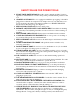
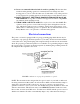
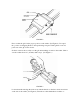
SAFETY RULES FOR POWER TOOLS 1. KNOW YOUR POWER TOOL-Read the owner's manual carefully. Learn its application and limitations as well as the specific potential hazards peculiar to this tool. 2. GROUND ALL TOOLS-If tool is equipped a with three-prong plug, it should be plugged into a three-hole receptacle. If an adapter is used to accommodate a twoprong receptacle, the adapter wire must be attached to a KNOWN GROUND. Never remove third the prong. (See Figure 1.) 3. KEEP GUARDS IN PLACE-and in working order.
20. It is not recommended that the lathe be used for grinding. The fine dust that results from the grinding operation is extremely hard on bearings and other moving parts of your tool. For the same reason, if the lathe or any other precision tool is kept near an operating grinder, it should be kept covered when not in use. 21. DON'T LET LONG, THIN STOCK PROTRUDE FROM THE BACK OF THE SPINDLE—Long, thin stock that is unsupported and turned at high RPM can suddenly bend and whip around. 22.
with an improper power source will burn out the motor or speed control. Also, the first few DC units built did not include the circuits to adapt to other currents. If you have an early DC model, remove the plastic speed control housing and look for a label on the aluminum speed control frame. If it has a small metallic label on top of the frame that lists input voltage as 120VAC, DO NOT ATTEMPT TO CONVERT TO OTHER CURRENTS.
• A chip guard (P/N 4360) is now available that offers additional protection from flying chips when working near the spindle. It is not a substitute for wearing proper eye protection but is an excellent level of additional protection. It will also contain cutting oil to help keep your work area cleaner.
Many fine books have been written on machining techniques and are available at your local library or book store. Although these books will be referring to machines many times larger than Sherline's tools, the principle remains the same. For the best reference that is specific to Sherline tools, see Joe Martin's book, Tabletop Machining. Lubrication • • • • • • MACHINE SLIDES-Use a light oil such as sewing machine oil on all points where there is sliding contact.
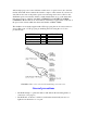
FIGURE 2 Next, see that the gib is in the proper position on the saddle. (See Figure 2.) It is taped into position for shipping. Remove the tape holding it in place. If the gib has come off, position it on the gib lock as shown. Set the dovetail of the crosslide over the gib and matching dovetail on the saddle. Slide it onto the saddle about 1/4" (6-7mm) until it stops. (See Figure 3.
engage the threads. Continue to crank the handwheel clockwise until the crosslide is in the desired position on the saddle. FIGURE 4 Mill-column mounting procedure The mill is shipped attached to a piece of plywood to keep it from moving in the box. Before you begin, remove the screws holding the mill base to the plywood. It was installed strictly for packing purposes and will need to be removed so that the column can be installed.
FIGURE 5 Set the column on the base aligned with the mounting holes and hold it in position while you insert the first screw up from the bottom of the base. Hand turn the first screw part way in and then start the second screw. This can be done with the machine upright by letting the base hang over the edge of your table or bench just far enough to expose the first hole. Using the hex key, snug up both screws lightly first, and then tighten evenly.
periodically when using the machine, as vibration from operation may cause some fasteners to loosen up. Mounting the motor and speed control unit to the headstock (Refer to the exploded views and number list for part number references.) FIGURE 6-DC Motor and Speed Control Assembly 1. Remove motor pulley from motor shaft. Mount the inner belt guard to the motor using the two standoffs (P/N 4310). Next install the motor pulley (P/N 4336) to the motor shaft and tighten the set screw.
belt is routed properly. Then secure the cover with (2) 1-3/8" pan head screws which go into nuts pressed into the back of the inner belt guard. 5. Attach motor mounting bracket to rear of headstock with two 10-32 x 3/8" socket head screws. There is enough "play" in the mounting holes to allow you to ensure the motor is visually mounted parallel with the spindle axis. (Note: If chip guard is to be mounted, its attachment screw replaces one of these mounting screws.
The advantages of Sherline's DC motor and electronic speed control Sherline's 90 volt DC motor is very smooth and powerful, particularly at low RPM. The specially designed electronics package also provides some unique advantages in addition to smooth speed control with a usable speed range of 70 to 2800 RPM. A special circuit compensates for load, helping to keep RPM constant.
Remember that the circuit breaker turns the speed control off which turns off the motor. If power were to be applied to the speed control with the motor disconnected, it could damage the speed control. Thermal protection is built into your motor to make sure it is not damaged by overloading. Use good common sense when operating the motor, and it will provide many years of trouble free operation.
FIGURE 7-Cross section of headstock showing locking screw. The screw in the front center of the headstock has a cone point. The pivot pin has a tapered slot with a corresponding angle. When the screw is tightened, its angled face engages the groove and, because the pivot pin can not come up, it draws the headstock down into position, clamping it into place. If the pin were rigid, it could keep the headstock from pulling down squarely. FIGURE 8-Headstock and alignment key in position over lathe.
The headstock is aligned with the lathe bed or column saddle with a precision ground key that fits into keyways in both parts. It is not square in cross section so it will fit in only one direction. Push the headstock firmly against it as you tighten the hold down screw. The mill headstock has two keyways milled into it so it can be mounted in conventional fashion or at a 90° angle for horizontal milling.
eliminates one of the best features of Sherline machines...the ability to easily be put away for storage. FIGURE 10-Plans for mounting board hole patterns. Confirm actual dimensions from your lathe or mill before drilling. The newly added model 2000 multi-direction mill can be mounted to a board 12" x 18" in a similar fashion. The mill may be mounted in a similar manner on a 10" x 12" to 12" x 24" pre-finished shelf board with rubber feet using 10-32 x 1" screws to attach the mill to the board.
Converting machines from inch to metric or vice versa All Sherline tools and accessories are manufactured in your choice of inch or metric calibrations. Converting a lathe or mill from one measurement system to the other is possible, but it takes more than changing the handwheels. The leadscrews, nuts and inserts must also be changed. A look at the exploded views of the machines on pages 27 and 28 will show which parts need to be purchased.
replace the mounting plate, pivot the speed control back down and refasten it. Moving the belt back to the other position is simply a reverse of the above procedure. Preload adjustment SPINDLE ADJUSTMENT-If any end play develops in the main spindle, it can be easily eliminated by readjusting the preload nut. (See part number 4016 in the exploded view.) When the headstocks are assembled at the factory, the preload nut is adjusted to .0002" (.005mm) of end play.
Backlash must be allowed for by feeding in one direction only. Example: You are turning a bar to .600" diameter. The bar now measures .622" which requires a cut of .011" to bring it to a finished diameter of .600". If the user inadvertently turns the handwheel .012" instead of .011", he couldn't reverse the handwheel just .001" to correct the error. The handwheel would have to be reversed for an amount greater than the backlash in the feed screws before resetting the handwheel to its proper position.
If excessive backlash develops at the handwheel and thrust collar junctions, adjust by first loosening the handwheel set screw. Index (rotate) the handwheel so the set screw tightens on a different part of the shaft. (If you don't, it may tend to keep picking up the previous tightening indentation and returning to the same spot.) Push the handwheel in tightly while holding the mill saddle and retighten the handwheel set screw.
machine cuts as straight as you can measure. There should be enough movement available without removing the key, as its factory placement is quite accurate. Take another test cut and remeasure. Repeat this procedure until you have achieved the level of perfection you seek. Then stand the lathe on end with the alignment key pointing up and put a few drops of LocTite™ on the joint between key and headstock. Capillary action will draw the sealant in, and when it hardens, the key will be locked in place.
The main purpose of using lubricants is to keep the chips from sticking to the cutting tool. When used properly, modern high speed tool bits are not likely to be affected by heat on the type of work usually done on Sherline tools. General machining terms Two terms frequently used in machining are "Feed" and "Cut". Reference to the diagrams below will show what is meant by these terms.
surface, occasionally digging in. The surface of the tool that is doing the most cutting will find a frequency of vibration that is a product of all the variables involved. This can cause anything from a high pitched whine on light, high speed cuts to a resonating racket that can rip the work out of the chuck on heavy cuts. If you maintain the same feed rate and reduce the RPM, the feed will increase because chip will be thicker.
Lathe Specifications FEATURE Swing over bed Swing over carriage Distance between centers Hole through spindle Spindle nose thread Spindle nose taper Travel of crosslide Tailstock spindle taper Protractor graduations Handwheel graduations Length overall Width overall Height overall Shipping weight Motor Spindle speed range 4000(4100) 3.50" (90 mm) 1.75" (45 mm) 4400(4410) 3.50" (90 mm) 1.75" (45 mm) 8.00" (200 mm) 17.00" (430 mm) .405" (10 mm) 3/4"-16 T.P.I. #1 Morse 4.
SHERLINE Lathe Operating Instructions (Reprinted from the Sherline Assembly and Instruction Guide, Fourth Edition (1997) CAUTION! Read all operating instructions carefully before attempting any machining operations! Review Safety Rules for Power Tools before beginning.
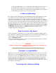
FIGURE 1--Parts of a Sherline lathe (Note: Tailstock locking screw is now relocated to a vertical position on the newer tailstocks. This drawing shows an older style tailstock without gib or cutout front face.) Leveling the Cutting tool Each type of turning work requires the correct tool for the job. It is important that the cutting tool is sharp and correctly set up in the tool post. The cutting edge of the tool should be exactly level with the center height of the lathe.
Initial Test Cutting If you have never operated a lathe before, we suggest that you make a trial cut on a scrap of material to learn the operation of the machine. In a 3- or 4-jaw chuck, secure a piece of round aluminum stock approximately 3/4" (19mm) diameter and 1-1/2" (38mm) long. Secure the presharpened 1/4" square cutting tool supplied with the lathe in the tool post, making sure that it is properly positioned. Turn the speed control all the way counterclockwise, and then turn the motor on.
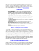
FIGURE 3—Holding a round work piece in a 3-jaw chuck. FIGURE 4—Holding a square work piece in a 4-jaw chuck. . Turning Between Centers This is done by fitting the dog to the work that is to be turned and placing the work and dog between the centers in the headstock and tailstock. The maximum diameter that can be held with the dog is 5/8" (15mm). (See Figure 5.
FIGURE 5—Turning between centers with a faceplate and drive dog. The dog is driven by fitting it into one of the faceplate holes. This method of turning is ideal for bar work or turning of steps on a bar. The tailstock center must be greased to prevent overheating. (An optional "live center"—such as P/N 1191—turning on ball bearings is the solution preferred by most machinists.) The headstock spindle has a Morse No. 1 taper in the spindle nose. The spindle thread is 3/4-16 TPI.
FIGURE 6—Center drilling. The work turns while the drill is stationary. See chart of commonly available center drill sizes. FIGURE 7--Center drilling a long work piece held in a steady rest. Tailstock Drilling Hold the work in a 3- or 4-jaw chuck. If the work is longer than approximately 3" (76mm), support the free end with a steady rest. Fit the drill chuck to the tailstock with a No. 0 Morse arbor and secure a center drill in the chuck.
center drill close to the work and lock in position. Turn the tailstock handwheel to bring the center drill forward. After the hole is started with the center drill, switch to a standard drill bit of the desired size to drill the hole. Headstock Drilling The drill chuck comes fitted with a #0 Morse arbor that fits in the tailstock spindle. To use it in the headstock you will need to first change to the #1 Morse arbor which is included with your lathe.
kind type work. Use them only when a boring tool cannot be used because of the depth of the hole. Because of their length, they cannot always be used on a small lathe. Reamers are used only to "clean up" the hole. To make an accurate hole, the work is drilled approximately .010" (.25mm) smaller than the reamer size. The work should be slowly rotated and the reamer slowly fed into the hole while applying plenty of cutting oil. The reamer should be frequently removed and cleared of chips.
FIGURE 9--Turning a taper with the Headstock rotated. Short work can be inserted in a 3- or 4-jaw chuck and turned as shown in Figure 9. If the headstock is angled towards the lathe front, the taper will cut smaller at the right. Tapers can also be bored in work held in the 3- or 4- jaw chuck. To machine a taper in longer stock, center drill both ends of the bar, set the headstock angle and mount the part between centers. (See Fig. 10.
The shaping of cutting tools to suitable angles for the type of material and nature of work being performed can be very important to satisfactory work. When tools become dull, gently re-grind and preserve the original angles and shapes. Do not grind the top face of the tools, but confine sharpening to the end and/or sides except form tools which are ground on the top surface. Remember that heavy cuts and rapid feed will cause greater strain on the chuck and lathe.
Parting —The conventional parting tool is shaped like a dovetail when viewed from above and is used to cut off work pieces by feeding the end of the tool across the lathe bed and through the work piece. The Sherline parting tool instead uses a thin .040" (1mm) blade which has a slightly thicker ridge at the top to accomplish the same job of providing clearance for the tool while cutting. Parting tools thicker than .040" (1mm) will be too thick for use on your Sherline lathe.
tool bits, correct clearances are essential or "rubbing" can occur. Turning Tools (left and right hand)—Reference to Figure 11 will illustrate the lateral positioning of this tool. Note the clearance behind the point between the end of the tool and the work. Insufficient clearance will cause the tool to "rub" and excessive clearance will produce a ridged or wavy finish due to the small length of tool edge in contact with the work. This ridging becomes more pronounced with rapid feed.
the finished diameter. Adjust depth of cut if necessary and complete the final pass using a SLOW feed to obtain a smooth finish and exact size. Cutoff or Parting Tool After completing a part in the lathe it is frequently necessary to separate the part from the excess material used for chucking. This operation is best accomplished with the use of a cutoff tool or "parting tool" as it is sometimes called.
The turning speed for parting should be about one half the normal turning speed and feed rate should be a little heavy so the chip will not break up in the slot. If speed and feed are correct, there will not be any chatter, and the chip will come out as if it were being unrolled. Cutting oil plays a major roll in this occurring properly. If the tool chatters, first check to see if the work is being held properly. Then decrease speed (RPM) or increase feed rate or both.
A slow rate of feed should be used as the turnings are not able to escape freely from the hole. Frequent withdrawal of the tool to allow turnings to escape may be necessary. Care should be taken not to feed the tool beyond the depth required or to feed so deeply as to damage the chuck or faceplate. Where a hole must be bored right through the work, it should be shimmed out from the faceplate to provide clearance for the tool to feed through.
holder that uses the P/N 7605 insert. This is a 55° insert good for turning, facing and profiling. Also available are 80° inserts which are slightly less versatile but offer longer tool life because of their stronger, more square shape. These tools should not be used to cut hardened steels or piano wire. Materials such as those should be ground to shape, not cut. Abrasive materials such as glass reinforced plastics can be easily cut with these tools.
NOTE: Never attempt to cut steel with a diamond cutter. While inserted tip carbide and diamond cutting tools will improve the performance of the Sherline Lathe, they will not correct poor machining technique. Rigid setups are a must for tools such as these. FIGURE 20—The Sherline W.R. Smith T-Rest T-Rest (P/N 2110) and Gravers Another method of removing metal is with a hand held cutting tool called a "graver". It is rested on and moved along a repositionable rest called a T-Rest.
FIGURE 21—The Sherline knurling tool holder. Knurling Tool (P/N 3004) Sherline's knurling system is designed to be used only with the Sherline Lathe. The knurling holder mounts directly to the crosslide. A good knurl is produced by embossing, not by cutting, and this creates high tool loads. Using two knurls opposing each other equalizes these loads allowing successful knurling on a small machine. A number of patterns can be achieved by changing the knurls.
Keep in mind that, apart from possible production of excessive heat and the fact that excessive speed may damage the cutting edge or cause it to "rub" instead of cutting, turning speeds are not too critical. Slower speeds than normal cause no harm, except by increasing the time involved. Aluminum, however, usually gives a better finish turned at high speed and lubricated. Use of Accessories and Attachments Your lathe can be made more versatile with the addition of suitable attachments and accessories.
Part Numbers and Descriptions, SHERLINE Lathes and Mills KEY TO MATERIALS: A=Aluminum, B=Brass, C=Composite, DC=Die Cast, P=Plastic, U=Urethane, S=Steel PART NO.
40221 (41221) 40220 (41220) 40230 40240 40250 40260 40270 (41270) 40280 40290 40300 40310 40320 40330 40340 40345 40370 40380 40390 40400 40420 40440 40500 40501 40510 40520 40530 40540 40550 40560 40570 40580 40590 40600 40620 40630 40640 Tailstock Feed Screw body only, Inch (Metric) Feed Screw, Inch (Metric) Headstock Spindle Headstock Pivot Pin, Lathe Tool Post Tee Nut Head Key Tailstock Spindle, Inch (Metric) Thrust Collar Leadscrew end Leadscrew Thrust 5-40 x 1" SHCS Bearing Washer 10-32 x 5/8" Skt.
40660 40670 40690 40760 40820 40860 40870 40890 (41890) 40900 40910 40980 40990 41080 41110 41130 43100 43110 43120 43130 43140 43150 43160 43170 43180 43190 43200 43230 43360 43450 43460 44010 44120 44200 (44230) 44210 (44220) 44211 (44221) 44880 3/16" I.D. Washer 10-32 x 1/2" Skt. Hd. Cap Screw 10-32 x 3/4" Skt. Hd. Cap Scrw 10-32 x 5/8" Thumbscrew Gib Lock Tailstock Locking Screw Grommet Tailstock Spindle Locking Screw Slide Screw Insert, Inch (Metric) 10-32 x 3/8" Flat Hd. Skt.
45010 (45160) 45040 45170 45180 45190 45450 or 45460 90060 90080 Leadscrew, Z Axis, Inch (Metric) Saddle, Z Axis Column Saddle Lock 3/16" Ball Bearing #10 Type B Washer 45450=DC Motor with externally replaceable brushes (Leeson) 45460=DC Motor with externally replaceable brushes (Hill House) (NOTE: We purchase motors from two different manufacturers to keep pricing competitive. Specifications on both are the same, but replacement motors should be ordered with the same part number as the original.
This double rotary table setup by Bob Breslauer of Ft. Lauderdale, Florida, is an example of the type of special setups Sherline tool owners sometimes develop. Standard Dimensions of Sherline Tools If you are making special tooling or a custom accessory for your Sherline tools, this will save you the trouble of measuring your particular machine to find a dimension, some of which are actually quite difficult to measure. If you need a dimension not listed here, please call or write with your request.
Pulley groove side angle Table T-slot centerline distance (lathe and mill) T-slot nominal dimensions** 19° 1.5" Slot width, top: .25" T width, bottom: .40" **Note: The T-slots are extruded into the material. Table Upper slot depth: .10" T Slot depth: .10" surfaces are machined for flatness, but the slots (Total depth: .20") themselves require no additional finishing processes. 20 threads per inch or Leadscrew thread pitch, inch .
±0.001" per inch of travel Leadscrew thread pitch accuracy COLLETS Sherline WW Collet body diameter 8 mm WW collets (by others), body diameter WW and 8 mm collet thread HEADSTOCK BEARINGS Designation/stock number (ZZ refers to "double shielded") Size of bore Tolerance of bore Outside Diameter Tolerance of OD Width Bearings 0.312" to 0.313" 0.314" to 0.315" .275-40 6004ZZ 20 mm (0.7874") 0.0004" 42 mm (1.6535") 0.0005" 12 mm (0.4724") 9 balls, 1/4" dia.
Sherline Lathe Dimensions The drawing below shows the key dimensions on a Sherline Model 4000 lathe. It is provided to help those who wish to make special equipment to fit to your lathe. If you wish to download a higher quality version of the drawing, it is also available as a .pdf file. Motor and Speed Control ELECTRIC MOTOR SPECIFICATIONS FROM MANUFACTURER • Type of enclosure: Totally enclosed, non-vented • Duty rating: Continuous--10 oz. in. at 6100 rpm, .85 amperes; Intermittent--30 oz. in.
• Speed in rpm: 6100 rpm continuous • Class of insulation: Class A, 105° (C.) insulation system • Normal full load current: .85 amperes • Starting current: 17 amperes instantaneous starting current (<100 milliamperes). This is also stall current in True RMS • Max current at time of changeover from lower speed to higher speed: Depends on load • Type of motor: 3.00 inch (outer diameter) sub-fractional horsepower brush-type permanent magnet motor • Temperature rise at ambient 50° C.
Hz, so Sherline machines can be plugged in and used in any country in the world without a transformer as long as you have the correct wall plug converter.. USE WITH AN INVERTER: This motor and speed control can be used with an inverter that produces a sine wave. It cannot be used with an inverter that produces a square wave.