
Instructions


WEAR YOUR
FORESIGHT IS BETTER
THAN NO SIGHT
READ INSTRUCTIONS
BEFORE OPERATING
SAFETY GLASSES
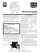
Installing Stepper Motors
6. Assure that the at on the motor shaft is still aligned
with the coupling set screw (observe the position of
the rear at or handwheel set screw—the two ats are
parallel) and tighten the coupling set screw. Install and
turn the handwheel and observe the movement of the
leadscrew to make sure everything is turning smoothly.
Using handwheels on the Stepper Motors
When turning an unpowered stepper motor by hand, you
may notice a slightly “notchy” feel because of the permanent
magnets in the motor; this is normal. When the motors are
powered up they lock in position, and it will be very dicult
to move them with the handwheels. Therefore, if you wish
to use manual mode, you should rst turn o the power
to the motors using the ON/OFF switch on the external
driver box or on the side of the computer if the driver box
is built in. Turning a DC motor by hand causes it to act as
a generator, sending current backward through the circuit.
However, low amounts of current will not damage the
board, so avoid cranking faster than about 1 rev/sec to be
safe. For longer travels, use LinuxCNC’s (formerly EMC)
jog mode for approximate positioning, then turn o driver
box power and use the handwheel for ne tuning.
Stepper Motor Installation Instructions
In order to prevent damage during shipment, some of the
stepper motors have not been pre-installed. Install them
using the following procedure:
1. If not already installed, carefully plug the white cable
connector into the slot in the motor. Orient the motor
so the plug is either on the right side or on the bottom
to keep chips and coolant from causing a possible
electrical short at the connection. If you wish, a small
amount of silicon sealant or hot melt glue can be used
to secure the white plug to the motor and seal the joint.
2. Note the location of the ats on the stepper motor
shaft. Always assure that the coupling and handwheel
set screws are tightened against the at on the shaft.
Tightening the set screw against the round part of
the shaft can gall the shaft and make it impossible to
remove from the coupling later.
3. Align the coupler set screw with the access hole in the
side of the stepper motor mount and assure that the set
screw is suciently released so that the motor shaft
can be inserted.
4. Insert the motor shaft into the coupling, making sure
the set screw is aligned with the at. Keep the motor
square to the mount so as not to ex the coupling during
insertion. Loosely tighten the set screw.
5. Install three 8-32 x 3/8" socket head cap screws (SHCS)
through the holes in the motor ange and into the
stepper motor mount holes. Instead of a 4th screw in
the four o’clock position use a tie wrap through that
hole to secure the wire bundle from the motor. This
will help relieve strain on the motor plug connection.
PRECAUTIONS
• Poor connections can cause arcing, which can burn out motors or control chips. Always make
sure plugs and connections are fully engaged and making good contact before powering up.
• Do not pull on wires to disconnect motor. Always grasp the plastic connector or the plug itself.
• In manual mode, crank handwheel no faster than 1 rev/second to avoid back-current.
3700-CNC, Pg. 3 of 4
12050
8-32 x 3/8" SHCS (4)
67127
STEPPER MOTOR
67105 COUPLING
w/ 40520 SET SCREW
67102
STEPPER MOTOR MOUNT
Use fourth Socket Head Cap
Screw here, or use a tie wrap
to attach wires at this corner.
CABLE CONNECTOR
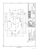
HOLES FOR MOUNTING TO MACHINE
(Holes on top as shown for mill X-axis and
lathe crosslide and leadscrew. Holes on
bottom for mill Y-axis.
PRELOAD NUT
Lathe Leadscrew—67104 (RH 1/4-28 for inch and metric)
X-axis and crosslide—67106 (67108 metric)RH
Y-axis and leadscrew—67107 (67109 metric) LH
Figure 1—Components of the stepper motor
and mount. The motor can also be mounted
with the electronic cable facing downward.
67111
8-32 x 7/8" SHCS (2)
67115
5-40 x 7/8" SHCS
67120
BALL BEARING (2)
TIE WRAP IN 4th MOUNTING HOLE
8-32 x 3/8" SHCS