
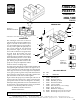
Instructions

MILL VISE PARTS LIST
REF PART
NO. NO. DESCRIPTION
1 35100 Vise body
2 35020 Movable jaw
3 35030 Fixed jaw insert
4 35040 Movable jaw insert
5 35120 Pull-down member
6 35060 Convex washer
7 35070 Flat head screw, 6-32 x 3/8 (2)
8 30561 T-nut, 10-32 (2)
9 35580 Hold-down clamp (2)
10 40330 Skt hd cap screw, 10-32 x 5/8" (4)
11 35130 Skt hd cap screw, 10-32 x 1-5/8"
INSTRUCTIONS
The advantages of this vise are obvious
when movement of the jaw is studied. (See
Figure 1 and look at the bottom of your
vice.) The tightening force (F1) produces
not only a force against the part (F2), but
also a force pulling the jaw downward
(F3). Therefore, angle “A” must exceed
45° in order to make force F3 greater than
F2. This keeps the movable jaw from
“tipping” back. Also note that extreme
clamping angles beyond 60° start to apply
much downward pressure but not much
horizontal force is directed to holding the
part. Moving the pull-down barrel to the
proper slot keeps the adjustment within
the most effective clamping range.
To clamp a part, place the jaw in approximate position and
start tightening the adjustment screw at an angle of 45° or
greater. (The back face of the moveable jaw is machined at
a 45° angle for reference.) If the angle of the adjustment
screw gets up to 60° or greater and you still haven't drawn
down on the part, loosen up the screw a little and move the
pull-down barrel to the next slot and retighten.
Figure 2 shows the proper way to hold a part in the vise. If
the part cannot be centered, use a spacer to help keep the
jaws parallel. This vise has been designed to accurately
hold objects being machined. It is not recommended for use
as a bench vise or for clamping parts in such a way and with
such force as to adversely affect its accuracy.
Joe Martin, President and Owner
Sherline Products Inc.
MILL VISE
P/N 3551
WRONG
RIGHT
SPACER
Figure 2—
Holding A
Work Piece
SHERLINE
PRODUCTS
INCORPORATED 1974
2/18/08
SHERLINE PRODUCTS INC. ˆ 3235 Executive Ridge ˆ Vista ˆ California 92081-8527 ˆ FAX: (760) 727-5857
Toll Free Order Line: (800) 541-0735 ˆ International/Local/Tech. Assistance: (760) 727-7857 ˆ Internet: www.sherline.com
EXPLODED VIEW
11
6
2
4
3
1
10
9
8
5
10
7
ADJUSTMENT RANGE:
46° TO 60°
Figure 1—
Pull-Down Feature
APPROXIMATE ADJUSTMENT SLOTS
F3
F1
F2
NOTE: To keep the surface of your table from being marred, we recommend you take a file
and slightly soften or deburr all the edges of the angle clamps that contact the table.