
Instructions

confidence it takes to do any job well. Too often, good
craftsmen are stopped from venturing forth because the
only information available shows the technically perfect
way to do things rather than the simple, practical methods
everyone really uses.
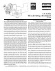
Thread cutting conversion kit
This kit has been engineered to add additional versatility to
your lathe. With this attachment, a wide variety of threads,
both right-handed and left-handed can be produced. Most
American standard and metric threads may be cut with
equal ease and precision. The accompanying charts list the
entire range from which you may choose. (See Figure 5.)
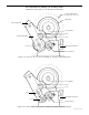
Conversion instructions (Refer also to illustrations)
1. Carefully drive the furnished small sheet metal screw into
the hole located in the spindle that extends from the left side
of the drive pulleys. Use a proper size screwdriver for this
operation and avoid installing the screw at an angle since it
must seat squarely against the spindle. After driving, remove
the screw and dress down any “burr” that is raised around
the edge of the hole. A small, fine file is suitable for this.
Next, slide two thin spacer washers over the tube and
against the pulley. Reinsert the sheet metal screw and
tighten firmly.
2. Remove the headstock. Locate the exposed flat head
socket screw in the top of the bed a loosen it a few turns.
3. From below, remove the cap screw under the base
directly below headstock. Note how may washers (if any)
are used with this screw. (Normally a 4000-series lathe
does not require any washers and a 4400-series lathe uses
one washer.)
4. Grease the sliding shaft with the flats on both ends and
slide it into the leadscrew support (situated directly below
the pulley). Be sure the end with the small flat enters first.
Now slide the fixed shaft with a single flat into the leadscrew
support. To guarantee that the shaft is fully inserted and
engaged, rotate it one or two revolutions while applying
gentle inward pressure to the end of the shaft.
5. Replace the screw from Step 3, making sure that the point
of the screw goes into the machined groove in the shaft.
Make sure also that any washers that were on this screw
are still in place. Check that the shaft is free to rotate. If the
shaft binds, first double check to assure that the end of the
cap screw is registered in the groove of the fixed shaft and
then add an extra washer under the screw head if needed
so it doesn’t go in quite as deep. Retighten the flat head
socket screw in the bed and replace the headstock.
6. Pull out the black plug on the front of the lathe base below
the name plate and slide the remaining shaft (with handle)
into the hole with the handle facing upward. It may be
necessary to rotate the shaft about 30° each way to get it to
completely seat and register with the sliding shaft.
NOTE: If insertion or movement of the engagement
lever is difficult, try loosening the two screws on the
bottom of the machine that hold the bed to the base.
Move the bed slightly until a good fit occurs.
7. It may be necessary to deburr parts for smooth operation.
NOTE: The section below entitled “Cutting A Thread for
Practice” uses the example of cutting a 28 pitch right-
hand thread on a 1/4" diameter piece of stock. The
following numbers are based on that setup.
Example: Setting up to cut a typical thread
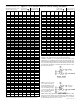
Refer to the chart (Figure 5) and select the type of thread
to be cut. As an example, we have chosen an American
standard, 28 TPI, right-hand lead.
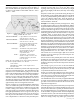
Figure 3
Setup for cutting 28 Threads Per Inch
GEAR A B C D E
TEETH 100 100 20 28 40
NOTE: Idler gear “E” is used for right-hand threads, idler gears “F”
and “G” are used for left-hand threads and are, therefore, not used in this
example.
Remove the motor assembly by removing the two socket
head cap screws that secure the motor mounting bracket to
the headstock and slip the drive belt off the pulley. (See the
Assembly and Instruction Guide that came with your
machine for more details if needed.)
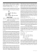
Slide gear “A” (100) onto the spindle engaging slot with the
previously installed sheet metal screw head.
Install gear “B” (100) and gear “C” (20) onto the primary
support arm. The drive pin is used not only to drive the “C”
gear, but also to hold the “B” gear on the arm.
Install gear “E” (40) on the secondary support arm.
Slide the lower split end of the
primary support arm over the
leadscrew support. Adjust until gear
“B” meshes properly with gear “A”
(100). When mesh is satisfactory,
tighten clamp screw.
Install gear “D” (28) and secure
with a hex head screw and small
washer. NOTE: This screw only
P/N 3100, Pg. 3 of 8
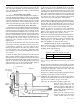
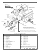
Side view, thread cutting attachment installed
Figure 2