
Instructions


Grinding, Pg. 3 OF 4
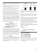
Grinding side 3
Rotate Tool
Approx. 15°
Grind until sparks
just reach tip of tool
A B
FIGURE 9—Grinding the “Hook” into side 3. When grinding
tools by hand, on average, the cutting-tip surface of the tool is
going to be .005” to .0010” below the top of the tool. This will
leave a .010” to .020” tit on the end of your tool when facing
o the part.
Use the skill you have developed grinding the second side
now. Set the blank on the support with the 10° (side 1) up.
The tool has to be brought up to the grinding wheel with a
slight angle so you don’t grind the tip below center. With
the tool setting on the rest, move the tool in and grind until
you see sparks bouncing o the cutting edge where the
corner of the wheel is lined up with the back part of the
10° face. When this happens, slowly decrease the angle
without pushing the tool in any more until sparks bounce
all the way to the tip. Stop as soon as this happens. On
most of our tool holders you can adjust the tool tip height
to compensate for the amount that you have ground o of
the top of your tool (generally .005" to .010"). However,
there is no adjustment on our compound slide. Therefore,
on the compound slide, the cutting tip of your tool needs
to be at the same height as the top of the tool blank. You
may inspect it, and the surface should be entirely ground.
The recommended way is to put more “hook” on the tool
than previously suggested, but we have found that the
slight increase in performance is oset by the problems
encountered re-sharpening these tools.
A
B
Side SideFront Front
FIGURES 10A—Normally recommended “hook” ground into
tool and 10B, Simpler method suggested for Sherline tools.
To put the nishing touches on your tool, you have to “kiss
o” sides 1 and 2 again. You must carefully line up side
1 with the wheel and bring it to the wheel in a positive
manner with very little pressure; watch for the sparks on
the cutting edge. What you’re trying to accomplish is to
make the tool set against the wheel on the same plane as
when you rst ground side 1. If the tool is held too rigid,
it will not align itself, too loose and it will bounce around.
“Breaking” the Point
Use the same method on side 2. The tool should be ready
to use except for the point. We recommend putting about
a .010 (.2 mm) “break” on the point by holding the tool
with the point aimed at the wheel face. Because two angles
converge at the point, the angle in relation to the sides is
greater. Think about it!
Top of Tool
Angles approximately equal
FIGURE 11—Putting a .010"
“Break” on the tip of the tool.
This means that if you set the tool at on the tool rest the
tool rest angle would have to be increased to get an even
at. This wouldn’t be worth the eort, so the easy way is
to free hand it. You should start by touching the heel of the
tool rst, and then change the angle until a slight at is put
on the tip. Of course, the angle you’re holding it at has to
be close when starting to get desired results.
FIGURE 12—Hand holding the tool to “Break” the point saves
resetting the angle on the tool rest.
The purpose of this at is to improve nish and tool life.
We don’t recommend a large radius on the tip of tools used
on small machines. These machines are not rigid enough
to get the desired results from this practice and cause
“chatter” problems.
The nished product should be a right handed tool, have
at cutting surfaces (except for the radius caused by the