
Service manual


Chapter 2 Principles
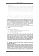
are transferred to the main board through the adapter board, thus to process and display the
data and waveforms. Commands from the main board, as well as the status information of
modules, are transferred through the adapter board. In addition, the adapter board adapts and
changes the power supply. The structure of the whole system is shown in the following figure.
---
As shown in Figure 2-14, the five modules and measurement cables monitor and measure
NIBP, SpO
2
, ECG/RESP/TEMP, IBP/CO and CO
2
in real time, and send the results to the main
board for processing and displaying. If necessary, the results are sent to the recorder for
printing.
The parameter monitoring functions are described respectively in the following sections.
2.1.1 ECG/RESP
■ ECG
The PM-9000 Express patient monitor has the following ECG functions:
1) Lead type: 3-lead, 5-lead, 12-lead
2) Lead way:
3-lead (1 channel):
5-lead (2 channels):
12-lead (8 channels):
I, II, III
I, II, III, aVR, aVL, aVF, V
I, II, III, aVR, aVL, aVF, V1-V6, CAL
3) Floating input
4) Right-foot drive
5) Lead-off detection
6) 2-channel ECG waveform amplification; processing ECG signals of any two leads
■ The ECG circuit processes the ECG signals. It consists of the following parts:
20