1AC Intelligent Wireless Router OPERATION INSTRUCTION STATEMENT Copyright © 2013 Yichen (Shenzhen) Technology Development Co.,Ltd. All rights reserved JCG is the registered trademark of Yichen (Shenzhen) Technology Development Co.,Ltd. Without explicit written permission of Yichen (Shenzhen) Technology Development Co.,Ltd. , any organization and individual are forbidden to imitate, copy, reproduce, translate this document or use it for other purposes.
Contents Chapter 1: Introduction 1.1 Purpose and conventions----------------------------------------------------------------------4 Chapter 2: Hardware installation 2.1 Description of panel indicator-----------------------------------------------------------------5 2.2 System requirements---------------------------------------------------------------------------7 2.3 Installation environment------------------------------------------------------------------------8 2.
Chapter 8: IPv6 setup------------------------------------------------------------------24 Chapter 9: Firewall setup 9.1 Port filtering--------------------------------------------------------------------------------------24 9.2 IP address filtering-----------------------------------------------------------------------------24 9.3 MAC address filtering-------------------------------------------------------------------------25 9.
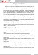
Chapter 1: Introduction Thank for you to purchase JCG 11AC dual-frequency wireless broadband router. This product integrates the functions of a router, switch, wireless access point and firewall and adopts the most advanced 11AC wireless technology, so the wireless transmission rate is improved by about 3 times compared to old 802.11N standard. This product supports 64/128 bit WEP encryption and advanced encryption and security mechanism such as WPA and WPA2.
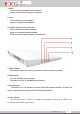
Chapter 2: Hardware Connection 2.1 Description of Panel Indicator: 1. Touch sensing status indicator To touch with a hand, an operator can turn on/off the status indicator. 2. Power indicator Off: power off Keep on: power on 3. USB status indicator Off: USB port not connected Off: USB port connected www.jcgcom.
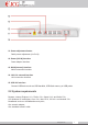
4. WPS Off: the wireless network not encrypted Keep on: the wireless network encrypted 5. QoS Off: QoS function not enabled Keep on: QoS function enabled 6.2. 4G/5G wireless status indicator Off: wireless network not enabled Keep on: wireless network enabled Flicker: wireless network data in transmission 7. RESET button To hold this button for over 5s, the device restores to factory setting. 8. WPS button To click, 5G WPS process starts. To hold for over 5s, 2.4G WPS process starts. 9.
11. Power adjustment button Radio power adjustment (x1.x5.x10) 12. Power (DC IN) interface Power adaptor interface 13. WAN (Internet) interface WAN connection interface 14. LAN 1-4 network interface LAN connection interface 15. USB 2.0 interface Connect USB device such as USB harddisk, USB flash memory or USB printer 2.2 System requirements Browser: Internet Explorer 6.0+, Firefox 2.0+, Opera 10.0+ and Safari 5.0+ OS: Windows XP and higher, Linux 2.4+, Mac OS X, iOS 4.0+ and Android 2.0+.
2.3 Installation environment Place the router horizontally Adjust the antenna angle to a proper direction Do not make the router close to the heating device Do not place the router under a damp environment. 2.4 Hardware installation steps Connect the router power with the accompanied power adaptor. Connect the broadband interface and router WAN interface with a network cable. For wired connection, connect the computer with the router LAN interface with a network cable.
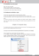
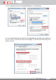
2) Select [Internet protocol version4(TCP/IPv4)] and click [Property] 3) Select [Automatically get IP address] and [Automatically get DNS server address], click [OK], return to previous interface and click [OK]. The system will automatically get IP address and DNS. www.jcgcom.
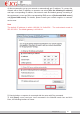
4) We recommend to set up your network to automatically get IP address. To connect the network with a fixed IP address, an operator can select [Use the following IP address] and input corresponding IP address, sub-network mask and default gateway. According to the requirement, a user can fill the corresponding DNS server at [Preferential DNS server] and [Spare DNS server]. For details, please consult your network supplier or customer service man. Note The default IP address is within 192.168.1.X(2≤X≤254).
Input command: Ping 192.168.1.1 and click Enter. If the following screen is shown, it indicates that the computer successfully connects the router. If the following screen is shown, it indicates that the device is not ready, please recheck the above steps. www.jcgcom.
Chapter 4: Quick Setup Wizard 1. Open the web browser 2. Input 192.168.1.1 at the browser address column and click Enter. Input a user name and password (the default is admin). 3. Enter the router interface. www.jcgcom.
4. Quickly set up the network (default routing mode) Set the wireless name and wireless password of the 5G wireless network at the position 1. Set the wireless name and wireless password of the 2.4G wireless network at the position 2. Set the network connection type of the WAN at the position 3 (the network connection mode is identified as follows:) Method 1: if you connect the Internet with a fixed IP, please select “static IP address” and input the information supplied by the broadband service supplier.
connected together via a bridge as the LAN interface. Network bridge mode – (access point) under this mode, all Ethernet interfaces and wireless network interfaces are connected together via a bridge. They connect each other easily and access the superior network via the Ethernet interface. The network bridge mode is also called as AP mode. Relay mode—(Client Repeater+AP) under this mode, the wireless network driver will virtualize a wireless client interface to connect the remote AP.
parameters for AP client. Wireless ISP mode—(relay WISP) under this mode, all Ethernet interfaces act as the LAN interface. The device connects the Internet via the wireless network interface. NAT is enabled. All LAN hosts access the Internet with same WAN IP addresses via the wireless network interface. You can select a wireless access point via scanning. Support multiple network connection modes such as static IP address, DHCP and PPPoE dialing.
Chapter 6: Wireless Setup To click the wireless setup main menu, the independent menu will display to set 5G and 2.4G wireless network parameters (WLAN1 represents 5G wireless network and WLAN2 represents 2.4G wireless network). The setup mode is basically same. Taking 2.4G wireless setup as one example: 6.1 Basic setup Basic setup: a user mainly sets up the basic parameters of the wireless network such as wireless network mode, SSID, channel and frequency.
Generic relay – the wireless network interface is used as the wireless network access point and wireless network client. The wireless network client interface can connect the superior router as the WAN interface (switch to wireless ISP mode and select correct WLAN wireless network interface). Extend wireless client interface SSID – it is the network name of the superior wireless network access point which the wireless network client should connect.
remote, or the clients are limited, even reach one. Beacon interval --- beacon is the small data packets which are used by AP to synchronize wireless network. The beacon interval indicates the interval of two beacons sent by AP. Short collision slot – it is used to shorten the communication time between AP and client. BG protection – a self-adjustment mechanism, which acts as 802.11B standard and can allow the clients meeting different standard can collaboratively work.
6.4 Access control Access control --- control connected client to forbid or allow them to connect and access your 2.4G wireless network. Allow access – only allow the clients in the list to access 2.4G wireless network. Forbid access – forbid the clients in the list to access 2.4G wireless network. Tip: 1.
Tip 1. Before WDS setup, select wireless network type as WDS or AP+WDS (AP+WDS is recommended) in wireless setup-basic setup, set the channel as it of the corresponding access point, click Apply and restart and further setup WDS. 6.6 WPS setup WPS (Wi-Fi protection setup) can allow your wireless network client to easily establish a connection with the wireless network of the device within several seconds.
6.7 Green wireless A use can disable or enable wireless network within the specified time. Please correctly set up the system time or enable automatic NTP update function. Otherwise, the green wireless may operate abnormally. Set up system time: router interface – system management – time zone setup Green wireless setup mode (taking the following demand as one example) From Monday to Friday, 2.4G wireless network is only enabled in the period from 18:00 to 24:00 and 2.
Chapter 7: Network Setup 7.1 LAN setup Set LAN IP address of the wireless router and access this wireless router via this IP address. Default gateway—it is valid only when the device works under the bridge connection mode and the default gate is the IP address of the device under other working mode. DHCP type – for the client, the LAN IP address will be obtained via other DHCP server in the network and need not be manually specified. For the server, it can allocate a IP address for the LAN; www.jcgcom.
DHCP effect domain – it specifies the effect domain of the IP address allocated by DHCP and generally it can be used by WINS service; 802.1d span tree protocol—it can detect and disconnect the network loop, avoid broadcasting storm and improve network stability 7.2 WAN setup Static IP address – manually set network connection information such as IP address, gateway and DNS server.
Chapter 8: IPv6 Setup To enable tunnel (6to4) setting, a user can quickly transfer the IPv6 data packets via the IPv4 network. Chapter 9: Firewall Setup 9.1 Port filtering It can restrict the hosts in LAN to access the Internet services at the specified ports or within specific port range. You can add multiple ports to restrict more Internet services. 9.2 IP address filtering It can restrict some hosts in LAN with specific IP address to access Internet.
9.3 MAC address filtering It can restrict some hosts in LAN with specific MAC address to access Internet. You can add multiple MAC addresses to restrict more hosts in the LAN to access the Internet. 9.4 Port forwarding You can establish self-network services in the LAN such as Web server and FTP server by adding the ports of related services to the port forwarding list. The port forwarding is only open to the specified ports or port range. www.jcgcom.
E.g. when a monitoring server in the Intranet with the address 192.168.1.8 provides the port forwarding service to the PC in the extranet (the service port is 7000 and HTTP port is 8000), the setup steps are described as follows: 9.5 URL filtering It can restrict some hosts in the LAN (such as children and employees) to access the specified URL addresses (web or website URL). You can add more URL addresses to restrict access to more URL. 9.
Tip: 1 When two or more VLAND VID is same, they will be consolidated into a VLAN automatically. 2 When the router works under the gateway mode, the final item (namely WAN port) must be checked. Otherwise, it will lead to network access failure. Chapter 10: USB Setup 10.1 User management With this function, you can manage the file sharing and FTP sharing users. E.g. add/delete a user or delete all users one time. www.jcgcom.
Add user – add file sharing and FTP sharing user. Anonymous user – allow to access file sharing and FTP sharing service in an anonymous mode. Note: when accessing the file sharing service in an anonymous manner, you must log in with [guest] as the sharing user name and the password must be empty. 10.2 Disk management Disk management: it displays the information on USB disk such as partition information, file system and residual space. Load disk – after the disk pops up, you can reload the disk partition.
After the file sharing is enabled, to click “Add sharing” at the sharing directory column, a user can set the privilege of the selected files on the disk. Notice: to click “Save/Apply”, your setting will take effect! If the files on the disk are shared, a user can view the sharing files as follows: input \\IP address of LAN port of router or press the combination button of “Windows+R”, input \\IP address of LAN port of router at the input column on the opened “Operate” dialog, a user can visit the sharing f
With FTP sharing setup, we can easily establish our FTP server and set related parameters and access privileges. We upload and download related documents via FTP server to facilitate use of corresponding users in LAN. The operations are described as follows: to input FTP://IP address of LAN port of router: FTP port (E.g. FTP://192.168.1.
10.6 iTunes sharing iTunes sharing: you can easily share music and video files on USB disk via itunes software on the PC. First enable iTunes sharing and click “Save/Apply”. and click “Set up sharing folder”, you can select the folders to share on the disk and click “Save/Apply”. To open “iTunes” media player and click “JHR-N865R-ITUNES” file name under sharing, a user can view the sharing media files on U flash stick or mobile disk and click a file to play. 10.
After a printer and router are connected, if the router successfully detects a printer after several seconds, the corresponding interface of the printer will display information on printer. Install (HP Laser Jet P1008) for printer. Take Window XP as one example 1. “Start” —— “Control panel” —— “Printer and fax” 2. Click left “Add printer” 3. Open “Add printer” installation wizard and click “Next”. www.jcgcom.
4. If the driver has been installed, select ”Keep existing driver(recommended)” or “Replace existing driver” and click “Next” 5. Enter printer name, click Next www.jcgcom.
6. Test the printer, click Next 7. Click Finish to complete printer installation. www.jcgcom.
8. (Take windows 7 operating system as an example) 1. StartControl PanelDevices and Printers 2. Right click to select Add a Printer 3. The Add printer wizard will appear as below fi gure, select “Add a local printer” and click Next www.jcgcom.
9. Select “Create a new port”, select “Standard TCP/IP Port” in “Type of port” and click Next 10. Enter IP address of the router in “Hostname or IP address” and click Next. Remember to uncheck “Query the printer and automatically select the driver to use” www.jcgcom.
11. Select the standard in “Device Type”, select “Generic Network Card “and click Next. 12. The following fi gure will appear after clicking. Select corresponding USB manufacturer and printer driver. We take HP LaserJet P1008 printer as an example. Please click “Have Disk....” if corresponding drivers are not found. www.jcgcom.
13. Click Browse... 14. Find the directory storing printer driver fi les and click "OK" 15. Find the driver corresponding to current printer in the list and click Next www.jcgcom.
16. Enter a printer name and click Next 17. Select Do not share this printer or Share this printer so that others on your network can fi nd and use it ” and click Next www.jcgcom.
18. Click “Print a test page”. The added printer is available if printing test page is successful. Click Finish, otherwise please reset according to above steps. Chapter 11: QoS Setup It can improve the experiences of the applications with higher priority such as online game by setting prioritized bandwidth to prevent some services from failure because too much system bandwidth is occupied by other network services (E.g. FTP or WEB). www.jcgcom.
E.g. the total extranet bandwidth includes 512Kbps for uploading and 8Mbps for downloading. Now it is required to restrict the maximum uploading bandwidth as 150 Kbps and maximum downloading bandwidth as 3000Kbps for the PC in the Intranet with IP address 192.168.1.8 and guarantee that minimum uploading bandwidth is 50 Kbps and minimum downloading bandwidth is 1000Kbps for another PC (MAC address is AABBCC888888). The setup steps are described as follows: www.jcgcom.
Chapter 12: Routing Setup The static routing allows you to forward routes for specific host or network, any access to this host or network will be forward by the default route. This case is applicable when another router R2 connects LAN port of this router RI. E.g. set the static routing of LAN. Shown as the figure, the hosts inside the R2 LAN can access the hosts in the R1 LAN. If the hosts in the R1 LAN access the hosts in R2 LAN, the static routing is set as follows in R1: IP address: 192.168.0.
Chapter 13: System Management 12.2 Data statistics Display the statistics information on data received and transmitted at different network interfaces, including statistics data at the wireless network interface and Ethernet interface 12.3 Dynamic domain It can map the dynamic IP address to the specified domain names. With dynamic domain service, a user can directly access the service provided by the device via the domain name without the need of caring change of IP address. www.jcgcom.
12.4 Time zone setup The system can be maintained and kept via NTP network time synchronization, so the timebased service and function can normally work. 12.5 DOS protection DoS is one frequent hacker attack means. It can attack the server by sending a large number of network connection requests and lead to no response to the normal user access requests and crash-down of the whole network service.
12.6 System log It can assist you to know and track the device operation records and easily locate and solve the device problems. A user can select type of log, all logs, wireless network log and DOS logs on demand. A user can remotely access the log server. www.jcgcom.
12.7 System diagnosis A user can know operation conditions of a PC and network via PING and TRACE ROUTE command in system diagnosis and quickly track routing path for IP transmission. 12.8 Firmware upgrade Upgrading the firmware to a newer version can optimize device performance or solve operation problems. Tip: The new firmware version can be uploaded and downloaded from JCG websitewww.jcgcn.
12.9 Setup management A user can back up, restore and recover the router setting via this interface. 12.10 Password setup Set the user name and password of login web. 12.11 Other setup This interface can set the displaying language of the wireless router interface and restart the router. www.jcgcom.
Logout After logout, a user can access setup page after login again. Chapter 14: FAQ Question 1: why can I not log into the router setup interface? 1. Please check whether the router port connects the computer port correctly 2. Check whether the network cable of the router is connected well and check whether the LED indicator of the router is on. If it is on, it indicates that the network cable is good. 3. Check whether the computer is installed with the agency software such as WinGate and SyGate.
8. If a user can not log into the router via the above operations, please restore the router to the factory setting and re-operate or contact our customer service support persons. Question 2: when the login user name and password of the JCG wireless router, how can I do? If a user forgets the login user name and password of a router, he can restore the router to factory setting. To find Reset button on the router panel, hold Reset button for over 5s and loosen it, the router will reset and restart.
1. Please confirm whether the LAN includes IP address of other device allocated by DHCP server is same as the IP address of the router allocated by DHCP server. If they are same, please change the default gate of the device or router to be in different network sections. 2. Confirm whether the LAN includes other DHCP server. If it is included, please shut down it. 3. Check the LAN computer and confirm whether another computer uses static IP address.
4. Antenna type of wireless router. The antenna can be changed to enhance wireless signals. 5. External factors the weather will have bigger influence on the wireless signals. The grey weather and thunder storm will lead to severe attenuation of signals. 6. Channel interference. When one channel includes multiple wireless routers, it will lead to bigger channel interference, please try to switch to cleaner channels and get better wireless network environment.
FCC Information and Copyright This equipment has been tested and found to comply with the limits for a Class B digital device, pursuant to part 15 of the FCC Rules. These limits are designed to provide reasonable protection against harmful interference in a residential installation. This equipment generates, uses and can radiate radio frequency energy and, if not installed and used in accordance with the instructions, may cause harmful interference to radio communications.