
User's Manual
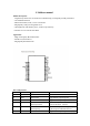

programmable strength
internal pull-up/down
chip select for SPI flash interface
7 PIO2 Bidirectional with
programmable strength
internal pull-up/down
Programmable input/output line
8 PIO1 Bidirectional with
programmable strength
internal pull-up/down
Programmable input/output line
9 PIO0 Bidirectional with
programmable strength
internal pull-up/down
Programmable input/output line
10 RST Input with weak internal
pull-up
Reset if low. Input debounced so must be
low for >5ms to cause a reset
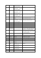
11 PIO11 Bidirectional with
programmable strength
internal pull-up/down
Programmable input/output line. PIO[11]
is data input for SPI flash interface
12 LED1 Open drain output LED driver
13 LED0 Open drain output LED driver
14 GND3 GND Ground connections
15 GND GND Ground connections
16 1V8 Power Positive supply for blue core
17 POWER_EN
/ Take high to enable both high-voltage
regulator and switch-mode regulator
18 BAT / Lithium ion/polymer battery positive
teminal. Battery charger output and input
to switch-mode regulator
19 CHG / Lithium ion/polymer battery charger
input
20 MIC_BIAS Analogue Microphone bias
21 MIC_P Analogue Microphone input, positive
22 MIC_N Analogue Microphone input, negative
23 SPKP_N Analogue Speaker output, negative
24 SPKP_P Analogue Speaker output, positive
25 MOSI with weak internal
pull-down
SPI data input
26 CLK Bidirectional with weak
internal pull-down
SPI clock
27 CSB Bidirectional with weak
internal pull-down
Chip select for SPI, active low
28 MIS0 Bidirectional with weak
internal pull-down
SPI data output
29 GND1 GND Ground connections
30 RF RF RF