
Use Instruction
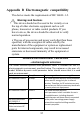
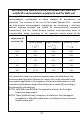
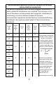
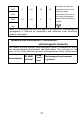
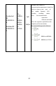
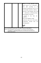
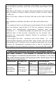
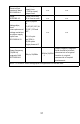
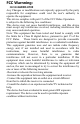
Table Of Contents
- 1.Introduction
- 2.Product introduction
- 3.Preparation before use
- 4.How to use
- 4.1Before use
- 4.2ECG lead wire, temperature probe and blood oxygen
- A.Use of ECG lead wire, body temperature probe and
- B.ECG lead wire placement
- Lead
- Color
- Body surface position (common name)
- 12-lead electrode cable
- RA
- White
- Intersection point between the midline of the righ
- LA
- Black
- The intersection of the left midline of the clavic
- RL
- Green
- Right lower abdomen (right leg)
- LL
- Red
- Left lower abdomen (left leg)
- V1
- Red
- Thoracic lead V1: the fourth intercostal space at
- V2
- Yellow
- Thoracic lead V2: the fourth intercostal space at
- V3
- Green
- Chest lead V3: midway between V2 and V4
- V4
- Blue
- Thoracic lead V4: midclavicular line at the fifth
- V5
- Orange
- Chest lead V5: at the front axillary line, at the
- V6
- Purple
- Chest lead V6: at the mid-axillary line, at the sa
- 6 lead electrode cable
- RA
- White
- Intersection point between the midline of the righ
- LA
- Black
- The intersection of the left midline of the clavic
- RL
- Green
- Right lower abdomen (right leg)
- LL
- Red
- Left lower abdomen (left leg)
- V1
- Red
- Thoracic lead V1: the fourth intercostal space at
- V5
- Orange
- Chest lead V5: at the front axillary line, at the
- 5 lead electrode cable
- RA
- White
- Intersection point between the midline of the righ
- LA
- Black
- The intersection of the left midline of the clavic
- RL
- Green
- Right lower abdomen (right leg)
- LL
- Red
- Left lower abdomen (left leg)
- V1
- Red
- Thoracic lead V1: the fourth intercostal space at
- 3 lead electrode cable
- RA
- White
- Intersection point between the midline of the righ
- LA
- Black
- The intersection of the left midline of the clavic
- LL
- Red
- Left lower abdomen (left leg)
- C.Spo2 probe placement
- D.Temperature probe placement
- 4.3Measurement process
- 4.4Data view
- 4.5 Charging
- 5.Care and maintenance
- 6.Attachment list
- Appendix A Specifications
- Appendix B Electromagnetic compatibility

32
where P is the maximum output
power rating of the transmitter in
watts (W) according to the
transmitter manufacturer and d is the
recommended separation distance in
metres(m). Field strengths from fixed
RF transmitters, as determined by an
electromagnetic site survey,
a
should be less than the
compliance
level in each frequency range
b
Interference may occur in the vicinity
of equipment marked with the
following symbol:
NOTE 1 At 80 MHz and 800 MHz, the higher frequency range applies.
NOTE 2 These guidelines may not apply in all situations. Electromagnetic
propagation is affected by absorption and reflection from structures,
objects and people.