
Use Instruction
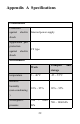
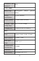
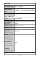
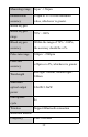
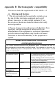
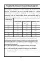
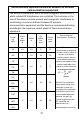
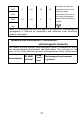
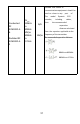
Table Of Contents
- 1.Introduction
- 2.Product introduction
- 3.Preparation before use
- 4.How to use
- 4.1Before use
- 4.2ECG lead wire, temperature probe and blood oxygen
- A.Use of ECG lead wire, body temperature probe and
- B.ECG lead wire placement
- Lead
- Color
- Body surface position (common name)
- 12-lead electrode cable
- RA
- White
- Intersection point between the midline of the righ
- LA
- Black
- The intersection of the left midline of the clavic
- RL
- Green
- Right lower abdomen (right leg)
- LL
- Red
- Left lower abdomen (left leg)
- V1
- Red
- Thoracic lead V1: the fourth intercostal space at
- V2
- Yellow
- Thoracic lead V2: the fourth intercostal space at
- V3
- Green
- Chest lead V3: midway between V2 and V4
- V4
- Blue
- Thoracic lead V4: midclavicular line at the fifth
- V5
- Orange
- Chest lead V5: at the front axillary line, at the
- V6
- Purple
- Chest lead V6: at the mid-axillary line, at the sa
- 6 lead electrode cable
- RA
- White
- Intersection point between the midline of the righ
- LA
- Black
- The intersection of the left midline of the clavic
- RL
- Green
- Right lower abdomen (right leg)
- LL
- Red
- Left lower abdomen (left leg)
- V1
- Red
- Thoracic lead V1: the fourth intercostal space at
- V5
- Orange
- Chest lead V5: at the front axillary line, at the
- 5 lead electrode cable
- RA
- White
- Intersection point between the midline of the righ
- LA
- Black
- The intersection of the left midline of the clavic
- RL
- Green
- Right lower abdomen (right leg)
- LL
- Red
- Left lower abdomen (left leg)
- V1
- Red
- Thoracic lead V1: the fourth intercostal space at
- 3 lead electrode cable
- RA
- White
- Intersection point between the midline of the righ
- LA
- Black
- The intersection of the left midline of the clavic
- LL
- Red
- Left lower abdomen (left leg)
- C.Spo2 probe placement
- D.Temperature probe placement
- 4.3Measurement process
- 4.4Data view
- 4.5 Charging
- 5.Care and maintenance
- 6.Attachment list
- Appendix A Specifications
- Appendix B Electromagnetic compatibility

32
2450
2
0.3
28
28
should be less than the
compliance level in each
frequency range.
Interference may occur in
the vicinity of equipment
marked with the following
symbol:
5240
0.2
0.3
9
9
5500
5785
Note 1: These guidelines may not apply in all situations. Electromagnetic
propagation is affected by absorption and reflection from structures,
objects and people.
Guidance and manufacturer
’
s declaration
–
electromagnetic immunity
The model Wireless dynamic multi-parameter holter is intended for use in
the electromagnetic environment specified below. The customer or the
user of The model Wireless dynamic multi-parameter holter should assure
that it is used in such an environment.
Immunity test
IEC 60601
test level
Compl
i
ance
level
Electromagnetic environment
– guidance