
Use Instruction
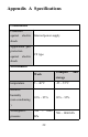
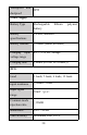
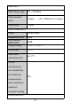
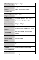
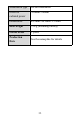
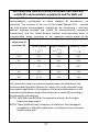
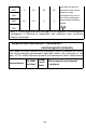
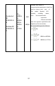
Table Of Contents
- 1.Introduction
- 2.Product introduction
- 3.Preparation before use
- 4.How to use
- 4.1Before use
- 4.2ECG lead wire, temperature probe and blood oxygen
- A.Use of ECG lead wire, body temperature probe and
- B.ECG lead wire placement
- Lead
- Color
- Body surface position (common name)
- 12-lead electrode cable
- RA
- White
- Intersection point between the midline of the righ
- LA
- Black
- The intersection of the left midline of the clavic
- RL
- Green
- Right lower abdomen (right leg)
- LL
- Red
- Left lower abdomen (left leg)
- V1
- Red
- Thoracic lead V1: the fourth intercostal space at
- V2
- Yellow
- Thoracic lead V2: the fourth intercostal space at
- V3
- Green
- Chest lead V3: midway between V2 and V4
- V4
- Blue
- Thoracic lead V4: midclavicular line at the fifth
- V5
- Orange
- Chest lead V5: at the front axillary line, at the
- V6
- Purple
- Chest lead V6: at the mid-axillary line, at the sa
- 6 lead electrode cable
- RA
- White
- Intersection point between the midline of the righ
- LA
- Black
- The intersection of the left midline of the clavic
- RL
- Green
- Right lower abdomen (right leg)
- LL
- Red
- Left lower abdomen (left leg)
- V1
- Red
- Thoracic lead V1: the fourth intercostal space at
- V5
- Orange
- Chest lead V5: at the front axillary line, at the
- 5 lead electrode cable
- RA
- White
- Intersection point between the midline of the righ
- LA
- Black
- The intersection of the left midline of the clavic
- RL
- Green
- Right lower abdomen (right leg)
- LL
- Red
- Left lower abdomen (left leg)
- V1
- Red
- Thoracic lead V1: the fourth intercostal space at
- 3 lead electrode cable
- RA
- White
- Intersection point between the midline of the righ
- LA
- Black
- The intersection of the left midline of the clavic
- LL
- Red
- Left lower abdomen (left leg)
- C.Spo2 probe placement
- D.Temperature probe placement
- 4.3Measurement process
- 4.4Data view
- 4.5 Charging
- 5.Care and maintenance
- 6.Attachment list
- Appendix A Specifications
- Appendix B Electromagnetic compatibility

32
Recommended separation distances between portable and
mobile RF communications equipment and the A&D unit
The model Wireless dynamic multi-parameter holter is intended for use in an
electromagnetic environment in which radiated RF disturbances are
controlled. The customer or the user of The model Dynamic ECG recorder
can help prevent electromagnetic interference by maintaining a minimum
distance between portable and mobile RF communications equipment
(transmitters) and The model Wireless dynamic multi-parameter holter as
recommended below, according to the maximum output power of the
communications equipment.
Rated maximum
output power of
transmitter (W)
Separation distance according to frequency of transmitter (m)
150kHz to 80MHz
d
[
3.5
]
P V 1
80MHz to 800MHz
d [
3.5
]
P E1
800MHz to 2.7GHz
d [
7
]
P E1
0.01
0.12
0.04
0.07
0.1
0.37
0.12
0.23
1
1.17
0.35
0.70
10
3.70
1.11
2.22
100
11.70
3.50
7.00
For transmitters rated at a maximum output power not listed above, the
recommended separation distance d in metres (m) can be estimated using
the equation applicable to the frequency of the transmitter, where p is the
maximum output power rating of the transmitter in watts (W) according to
the transmitter manufacturer.
NOTE 1 At 80 MHz and 800 MHz, the separation distance for the higher
frequency range applies.
NOTE 2 These guidelines may not apply in all situations. Electromagnetic
propagation is affected by absorption and reflection from structures,
objects and people.