
Use Instruction
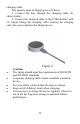
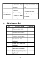
Table Of Contents
- 1.Introduction
- 2.Product introduction
- 3.Preparation before use
- 4.How to use
- 4.1Before use
- 4.2ECG lead wire, temperature probe and blood oxygen
- A.Use of ECG lead wire, body temperature probe and
- B.ECG lead wire placement
- Lead
- Color
- Body surface position (common name)
- 12-lead electrode cable
- RA
- White
- Intersection point between the midline of the righ
- LA
- Black
- The intersection of the left midline of the clavic
- RL
- Green
- Right lower abdomen (right leg)
- LL
- Red
- Left lower abdomen (left leg)
- V1
- Red
- Thoracic lead V1: the fourth intercostal space at
- V2
- Yellow
- Thoracic lead V2: the fourth intercostal space at
- V3
- Green
- Chest lead V3: midway between V2 and V4
- V4
- Blue
- Thoracic lead V4: midclavicular line at the fifth
- V5
- Orange
- Chest lead V5: at the front axillary line, at the
- V6
- Purple
- Chest lead V6: at the mid-axillary line, at the sa
- 6 lead electrode cable
- RA
- White
- Intersection point between the midline of the righ
- LA
- Black
- The intersection of the left midline of the clavic
- RL
- Green
- Right lower abdomen (right leg)
- LL
- Red
- Left lower abdomen (left leg)
- V1
- Red
- Thoracic lead V1: the fourth intercostal space at
- V5
- Orange
- Chest lead V5: at the front axillary line, at the
- 5 lead electrode cable
- RA
- White
- Intersection point between the midline of the righ
- LA
- Black
- The intersection of the left midline of the clavic
- RL
- Green
- Right lower abdomen (right leg)
- LL
- Red
- Left lower abdomen (left leg)
- V1
- Red
- Thoracic lead V1: the fourth intercostal space at
- 3 lead electrode cable
- RA
- White
- Intersection point between the midline of the righ
- LA
- Black
- The intersection of the left midline of the clavic
- LL
- Red
- Left lower abdomen (left leg)
- C.Spo2 probe placement
- D.Temperature probe placement
- 4.3Measurement process
- 4.4Data view
- 4.5 Charging
- 5.Care and maintenance
- 6.Attachment list
- Appendix A Specifications
- Appendix B Electromagnetic compatibility
21
After the measurement is over, the data measured in the
holter can be transmitted to the PC or mobile device software
for viewing via USB data cable or Bluetooth.
USB data cable to achieve data export steps:
1) Connect the holter to the PC via a USB data cable
2) Open the supporting software on the PC side
3) According to the PC terminal prompt, realize the
export data
Steps to realize data export in Bluetooth mode:
1) Turn on the Bluetooth function of the mobile device
and make sure that the Bluetooth function of the mobile
device is turned on.
2) Through pairing on the mobile device, after the
pairing is successful, the data is exported according to the
prompt of the mobile device.
Note:
The maximum storage capacity (recording time) of the
holter data is 72 hours.
4.5 Charging
This device uses a rechargeable lithium battery. It can be
charged by connecting a laptop or power adapter with a