
User's Manual
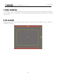
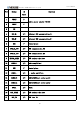
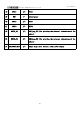
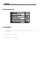
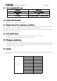

Table Of Contents
- 1.Product introduction:
- 2.Pin description
- PIN
- Symbol
- IO Types
- Function
- 1
- VDDIN
- P
- Module power supply PIN(5V)
- 2
- VDDIN
- P
- 3
- NC
- 4
- USB_D+
- I/O
- External USB communication D+
- 5
- USB_D-
- I/O
- External USB communication D-
- 6
- GND
- P
- Ground plane
- 7
- UT0_TX_CPU
- I/O
- CPU communication TX
- 8
- UT0_RX_CPU
- I/O
- CPU communication RX
- 9
- MR133_AWAKE
- I/O
- CPU awakens the foot
- 10
- SPKER +
- I/O
- audio amplifier+
- 11
- GND
- P
- Ground plane
- 12
- SPKER -
- I/O
- - audio amplifier-
- 13
- RADR_TX
- I/O
- UART4_TXD(user serial port)
- 14
- RADR_RX
- I/O
- UART4_TXD(user serial port)
- 15
- GPIO1
- I/O
- GPIO1
- 16
- MCU_AWAKE
- I/O
- MCU awakens the foot
- 17
- USB_ID
- I/O
- USB line ID
- 18
- GPIO2
- I/O
- GPIO2
- 19
- GND
- P
- Ground plane
- 20
- GPIO3
- I/O
- GPIO3
- 21
- GPIO4
- I/O
- GPIO4
- 22
- DUBUG_RX
- I/O
- UART_Log_RXD (for printing the internal informatio
- 23
- DUBUG_TX
- I/O
- UART_Log_TXD (for printing the internal informatio
- 24
- LDS_PWRON_OUT
- I/O
- Output high level control radar power supply
- 3.Electrical characteristics:
- 4.RF Characteristics
- 5.1 List of applicable FCC rules
- 5.2 Limited module procedures
- 5.3 Summarize the specific operational use condit
- 5.4 Trace antenna designs
- 5.5 RF exposure considerations
- 5.6 Antennas
- 5.7 Label and compliance information
- 5.8 Information on test modes and additional test
- 5.9 Additional testing,Part 15 Subpart B disclaim

- 深圳云视科技开发有限公司
产品规格书
5
5.1 List of applicable FCC rules
Parameter
Description
Operation band
2.400 to 2.4835GHz
Power
<5W
FCC rules
FCC Part15 Subpart C, Section 15.247
5.2 Limited module procedures
This module is an unrestricted module
5.3 Summarize the specific operational use conditions
The module is limited to OEM installation ONLY. The OEM integrator is responsible for ensuring
that the end-user has no manual instruction to remove or install module.
The module is limited to installation in mobile application; A separate approval is required for
all other operating configuration.
5.4 Trace antenna designs
The module is connected with an external antenna through a RF connector.
Product specification:41x7x0.6mm(No glue and cable)
5.5 RF exposure considerations
FCC Radiation Exposure Statement:
This equipment complies with FCC radiation exposure limits set forth for an uncontrolled
environment. This equipment should be installed and operated with minimum distance 20cm
between the radiator & your body.
5.6 Antennas
The WIFI part of the module needs an external antenna, and the gain of each frequency band
of the antenna is:
Gain
Frequency(MHz)
Value(dBi)
2400
2.2
2410
2.4
2420
2.5
2430
2.6
2440
2.7
2450
2.7
2460
2.6
2470
2.5
2480
2.5
2490
2.4
2500
2.2