
User Guide
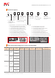
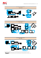
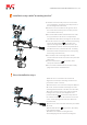
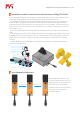

Installationstepswith"mountingbracket”
①Calculateandmeasurethepositionofonesideofthe
sensorinstallation,andpunchholesinthepositionof
theunlockinghandleontheback;
②Rotatethesensorscrewslidertotheoppositesideof
thescrewheadtobefixed(each90°rotationprovides
fourinstallationdirections);
③TheactuatorwithfourM4screwfixedatthesideofthe
door,payattentiontotheneedtotokeepbackthe
unlockknobsandhandlesmountingholesnotobscured;
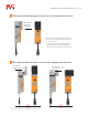
④Inserttheactuatorsensorjack,(mechanicallocksetting
needtounlocktheknobtologolocation)and
adjust"mountingbracketinstallationdirection"(for
eachinstallationrotate90°direction,itprovidesthree
installationdirection),withfourM4screw"mounting
bracketandactuatorlock,withsensors,bothspacing
shallnotbegreaterthan3mm;
⑤Theassemblyofthe"mountingbracket"andthe
actuatorisfixedontheothersideofthesafetydoorwith
2M4screws;
⑥Turntheunlockknobtologoposition,TRL1
safetylockcanworknormally;
⑦Thefouractuatorinstallationholeanti-disassembly
plugintotheactuatorinstallationhole.
②
④
⑤
①
③
③
④
④
⑥
④
①
⑤
④
④
④
④
③
③
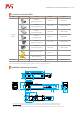
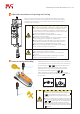
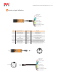
Directinstallationsteps
①Turnthesensorscrewslidertothescrewhead
alignmenttobefixed(fourmountingorientationsare
providedforeach90°rotation);
②Fixtheactuatorononesideofthesafetydoorwithfour
M4screws,andensurethatthemountingholesofthe
unlockingknobandhandleonthebackarenotblocked;
③Inserttheactuatorintothesensorjack(mechanical
lockingneedstorotatetheunlockingknobtothe
positionmarkedby),andmeasurethepositionof
theactuatormountinghole.Theactuatorisclosetothe
sensor,andthespacingbetweenthetwoshallnotbe
morethan3mm;
④Fixthesensorontheothersideofthesafetydoorwith4
M4screws;
⑤Tounlocktheknobtologoposition,TRL1safety
lockcanworknormally;
⑥Installthefouractuatormountingholeanti-
disassemblyplugsintotheactuatormountinghole.
②
①
③
④
⑤
④
②
②
②
SHENZHENTONGCHUANGMECHANTRONICSCO.,LTD.