
User Guide
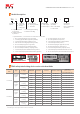
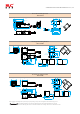
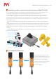

Interfacesignaldefinition
Plug
1
2
3
4
5
6
7
8
Socket
7
6
5
4
3
2
1
8
Brown24V
Blue0V
BlackinputA+
YellowinputB+
WhiteoutputA
GreenoutputB
Greyauxiliaryoutput
PinkLOCK/
UNLOCK
Brown24V
Blue0V
BlackinputA+
YellowinputB+
WhiteoutputA
GreenoutputB
Greyauxiliaryoutput
PinkLOCK/
UNLOCK
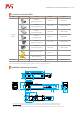
S/N
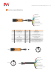
Signaldefinition
Colour
Explain
1
2
3
4
5
6
7
8
24V
Brown
0V
Blue
White
SafetyoutputA
Green
SafetyoutputB
Grey
Auxiliaryoutput
LOCK/UNLOCK
Pink
Yellow
SafetyinputB+
Black
SafetyinputA+
LOCK/UNLOCK
Safetyoutput
Powersupplynegative
Powersupplypositive
Safetyoutput
Cascadeinputs(monitored)
Doorstatus/lockstatus/outputstatus
Cascadeinputs(monitored)
SHENZHENTONGCHUANGMECHANTRONICSCO.,LTD.