Contents 1Introduction................................................................................................................................................. 3 1.1 Application background ........................................................................................................................... 3 2 System (the) introduction ................................................................................................................................... 4 2.
We declare that: ※ the product is installed with battery separately in the box. The FCC ID label is placed on Mobile Payment Terminal clearly visible to all persons at the time of purchase. ※ the user is cautioned that changes or modifications not expressly approved by the manufacturer could void the user’s authority to operate the equipment. ※ This device complies with part 15 of the FCC Rules.
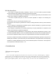
2 System (the) introduction 2.1 System composition and principle block diagram in the paper 2.1.1 Diagram of the system of the Cell phone signal amplifier communication schemes 2.1.2 System principle outlined 1. This product is suitable for WCDMA、CDMA and GSM type of network。 2. Cell phone signal amplifier (and amplifier for synonyms hereinafter referred to as the amplifier), amplifiers, feeder, antenna etc。 3.
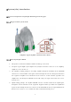
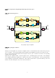
2.2 The composition and principle block diagram in the paper 2.2.1 The block diagram of 850M UP_LNA filter UP_PA duplexer duplexer DW_PA Combiner filter DW_LNA Combiner x2 x1 f(x1...xn) u1 u1 x1 f(x1...xn) INDOOR x2 UP_LNA filter OUTDOOR UP_PA duplexer duplexer DW_PA filter DW_LNA 1900M The principle diagram amplifier 2.2.
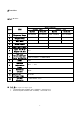
3Function 3.1.1 Rf index Specification Nmber 1 Frequency Range 2 Output Power 3 Max .Gain 4 Noise Figure 5 850MHz ITEM band 1900MHz Uplink Uplink Downlink 824~849MHz 869~894MHz 1850~1910MHz 1930~1990MHz 19±2dBm 11±2dBm 19±2dBm 10±2dBm 59±2dB 62±2dB 59±2dB 62±2dB ≤6dB ≤7.5dB Amplitude ripple ≤6dB ≤14dB Input V.S.W.R/ ≤2.0 Output V.S.W.R Spurious 9kHz~1GHz ≤ -36dBm/100KHz Emission&Output inter-modulation 1GHz~12.
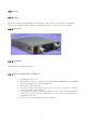
3.2 structure 3.2.1 cooling The overall structure and the floor flats and combinations。The bottom、Cover for the metal aluminium material,Heat dissipation good。Internal electroplating metal layer,Can effective signal, shielding。 3.2.2 appearance 3.2.3 installation Add install board, wall hung installation 3.2.4 Interface and function is introduced 1. 2. 3. 4. 5. 6.
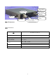
Status indicator Power source The indicator INDOOR USB+5V OUTDOOR 4 performance Power amplifier state selector switch Gain selected switch 4.1 environment Technology parameters NO. Working temperature -30℃~70℃ Storage temperature -30~70℃ Relative humidity 95%(30℃) vibration 10Hz~30Hz,0.38mm 30Hz~55Hz,0.