
User's Manual


6
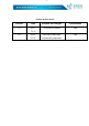
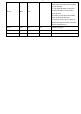
pin number
pin name
Chip pin name
input /Output
illust
rate
Pin1
GND
GND
-
Module ground wire GND
Pin2
VCC
VCC
-
Module Power 2.0 ~ 3.6V
Pin3
IO10
P10
I/O
Common IO port
Pin4
IO11
P11
O
Connection
status
indication
0: bluetooth
connected
1: bluetooth not connected
Pin5
RES
RES
I
Reset input pin, active low, no internal
pull-up
Pin6
EN
P12
I/O
Module enable control line (active
low)
0: The module starts broadcasting
until connected to the mobile device
1: Immediately enter a full sleep
state regardless of the current state
of the module
Pin7
SWC
SWC
-
Module firmware download TX
Pin8
SWD
SWD
-
Module firmware download RX
Pin9
IO13
P13
I/O
Common IO port
Pin10
IO02
P02
I/O
Common IO port
Pin11
IO03
P03
I/O
Common IO port
Pin12
IO04
P04
I/O
Common IO port
Pin13
IO05
P05
I/O
Common IO port