
Data Sheet
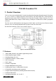
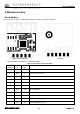

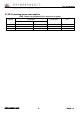

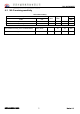

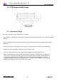
Table Of Contents
- 2.Module interface
- Pin definition
- Description: P identifies the power supply pin, I/O represents the input and output pins, and AI represents the analog input pin.
- 3. Electrical parameters
- 4 RF characteristics
- 5 antenna information
- When using a PCB on-board antenna on a Wi‐Fi module, to ensure optimal Wi‐Fi performance, it is recommended that the antenna portion of the module be at least 15 mm away from other metal parts.

T102 DATASHEET
深圳市盛创威科技有限公司
6
Version 1.0
3.4 Power consumption in working mode
Table 6 T102 operating current
Operating mode Working condition, Ta=25°C average
value
unit
Fast connection network
status
The module is in the state of fast connection network, and
the WI-FI indicator flashes quickly.
120 mA
Hot spot distribution
status
The module is in the hotspot distribution network, and the
WI-FI indicator flashes slowly.
122 mA
Network connection
status
The module is in a networked state and the Wi-
Fi indicator is
always on.
51 mA
Network disconnection
status (try networking)
The module is in the working state of disconnected network
(trying to connect to the network), and the Wi-Fi indicator is
always off.
116 mA
4 RF characteristics
4.1 Basic RF characteristics
Table 7 Basic RF
characteristics
Parameter item
Detailed description
working frequency
2.412~2.484GHz
Wi
-Fi standard
IEEE 802.11b/g/n (channels 1
-14)
Data transfer rate
11b:1,2,5.5, 11 (Mbps)
11g:6,9,12,18,24,36,48,54(Mbps)
11n:BW20_MCS7 65Mbps
11n:BW40_MCS7 135Mbps
Antenna type
PCB antenna (default)
4.2 Wi-Fi output power
Table 8 TX continuous
transmission power
parameter Minimu
m value
Typical
value
Maximum
unit
mode rate dBm
RF average output power, 802.11b CCK Mode
11M 14 16 18 dBm
RF average output power, 802.11g OFDM Mode
54M 12 14 16 dBm
RF average output power, 802.11n OFDM Mode
BW20_MCS7 11 13 15 dBm
RF average output power, 802.11n OFDM Mode
BW40_MCS7
11
13 15 dBm
Frequency error -10 - 10 ppm