
Data Sheet
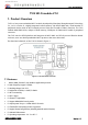
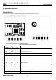

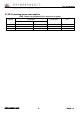

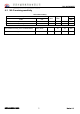

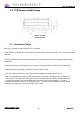
Table Of Contents
- 2.Module interface
- Pin definition
- Description: P identifies the power supply pin, I/O represents the input and output pins, and AI represents the analog input pin.
- 3. Electrical parameters
- 4 RF characteristics
- 5 antenna information
- When using a PCB on-board antenna on a Wi‐Fi module, to ensure optimal Wi‐Fi performance, it is recommended that the antenna portion of the module be at least 15 mm away from other metal parts.

T102 DATASHEET
深圳市盛创威科技有限公司
3
Version 1.0
2.Module interface
Pin definition
The T102 has 2 rows of 11 pins with a pin pitch of 2mm, as shown in Figure 1:
Figure 2 T102 front view Rear view
The interface pin definitions are shown in Table 1:
Table 1 T102 interface pinout description
Serial
number
symb
ol
IO
type
Features
1 VDD P Module power supply pin (3.3V)
3 GND P Power reference ground
5 A18 I/O GPIO_A18/UART0_RXD
7 A23 I/O GPIO_A23/UART0_TXD
9 A14 I/O GPIO_A14/PWM0
11 A15 I/O GPIO_A15/PWM1
2 A12 I/O GPIO_A12/PWM3
4 A0 I/O GPIO_A0/PWM2
6 A5 I/O GPIO_A5/PWM4
8 A30 I/O GPIO_A30/DEBUG_LOG_TX
10 A29 I/O GPIO_A29/DEBUG_LOG_RX