
User's Manual
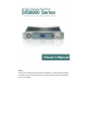

Owner’sManual
4
positionfix,temperature,fieldstrength,powerandotherinformation,seeP7.
6. CCM module: carrier controller, work mode of base station can be set via
software.
7. Local management port: with a dedicated coder, you can manage relevant
inf ormation settings of the base station. See P11 for cabling sequence and
settingme
thodsindetail.
8.Operatingknob:usedforoperatingthechannelmenu,andcurrentlycanbe
usedtocontrolthespeakerswitch.
9.Speaker:inanalogmode,whenthespeakerisenabled,youcanmonitorthe
currentcall.
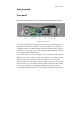
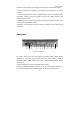
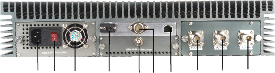
Rearpanel
From Fig.2, you see the rear view of the base station, which consists of four
modules,i.e.,thepowersupplymoduleontheleft,poweramplifiermodulein
theuppermiddle,TX&RXmoduleinthelowermiddle,andtheduplexermodule
ontheright.
1.Powersupplyport:connectto220VACpo
wersupply.
2.Powerswitch&LEDindicator:switchto
“┃”toturnonthepower;switchto“○”
tocutoffthepower.TheLEDindicatorlightsupredwhenthepowerison.
Figure2 - Rear Panel
①
② ③
④
⑤
⑥
⑦
⑧
⑨
⑩