
User's Manual
Owner’sManual
21
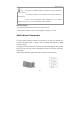
DipSwitch&ChannelNumberSettings
Thesettingsofdipswitch(seeFig.1‐③)shouldbecorrespondingtothesettingsof
channelnumberofthenetworkmanagementterminal(seesoftwareinstructionsfor
details).Asforasinglecarrierchannel,thecorrespondingmethodcanbe
summarizedinthisformula:channelnumber=Dipnum
ber*2‐2.Thedipnumber
canbesetaccordingtothecorrespondingchannelposition.
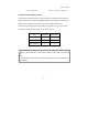
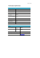
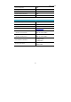
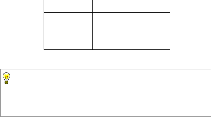
S.N. Dipswitch ChannelNo.
Basestation1 1 0
Basestation2 2 2
Basestation3 3 4
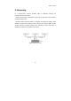
Figure 7-Row Cable
Channel Connection Diagram
Note:1.Dipswitchesareinpairs(upperandlower),bothneedtobeswitched
toON!
2.Channelnumbershouldbeevennumber,wrongsettingsmaycausemalfunction
ofbasestation!