To user, Thank you for choosing Shenzhen Samhoo Sci&Tech Co.,Ltd. transceiver products. To mostly enjoy the convenience of our products, please read this manual before you use the product.
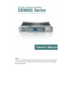
Owner’s Manual Models Instruction This manual applies to SIS8800 series products: SIS8811 (with basic transceiving function) SIS8813 (With IP Connection function) SIS8816 (with IP link/DMR/pseudo simulcast functions) SIS8819 (with trunking function) Notes ◇When operating an amateur base station, it is important to observe all the proper rules of conduct and not to cause harmful interference to other stations, during fix installed. ◇ Penalties will be imposed on those who operate transmitters illegally.
Owner’s Manual Contents Getting started ................................................................................................ 3 Front panel ............................................................................................. 3 Rear panel ............................................................................................... 4 Structural & Functional Features ............................................................ 5 Basic Operations ..........................................
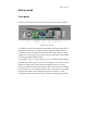
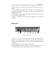
Owner’s Manual Getting started Front panel Remove the front panel,you can see the structure of the base station as follows: Figure1 - Front panel 1. Temperature control fan: used for heat dissipation, when the temperature is detected to be above 45℃, it rotates to enhance dissipation of the equipment. 2. Satellite module: The satellite module works with satellite antenna, which is installed in the upper right corner of the satellite module. Note: Some models are not equipped with satellite module. 3.
Owner’s Manual position fix, temperature, field strength, power and other information, see P7. 6. CCM module: carrier controller, work mode of base station can be set via software. 7. Local management port: with a dedicated coder, you can manage relevant information settings of the base station. See P11 for cabling sequence and setting methods in detail. 8. Operating knob: used for operating the channel menu, and currently can be used to control the speaker switch. 9.
Owner’s Manual 3. Cooling fan: The moment when the power is turned on, the cooling fan rotates for about 2 seconds; When the base station is in operation and the temperature is over 45℃, the fan starts to rotate for dissipation. 4. Battery port: 12V power supply or battery power supply. When the power supply module (220V) is in normal operation, the port is in charging/idle state, functioning as a standby power supply; In case of power module failure/power cut‐off, the standby power is used.
Owner’s Manual Structural & Functional Features Structural Features: 1. Fit for the 19 inch standard cabinet 2. All‐aluminum alloy workmanship & large‐area heat dissipation design 3. Configured with a broadband duplexer slot, and optional built‐in duplexer 4. Realizing integration of the CCM module, TX&RX module, power supply module and duplexer, and can be put to used after attaching the antenna, even without an engineering cabinet. 5.
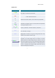
Owner’s Manual Display Icons Display Icons CON/SVC Link Meaning and Status Description CON (in yellow)‐‐The channel is control channel. SVC (in green)‐‐The channel is voice channel. Cable link status: In Green ‐ cable link in smooth connection; In Red ‐ cable link disconnects. CH X stands for the channel number, an even number set up by software. X TEM X stands for the temperature of the base station. In normal circumstances, the figure it shows is in Green.
Owner’s Manual The block at the top right of the scale is the TX power indicator. When the base station is not transmitting, the LED block indicator is in dark purple; when it is transmitting, the LED lights up solid green.
Owner’s Manual Basic Operations Installation & Module Inspection Open the package, check whether all modules are firmly installed in the base station. See Fig. 2 for completion of installation. To install the modules correctly, you must: * Power off the base station before installation. * Find the location of modules, take care to their groove direction and the pins inside the base station, and insert the module into the base station in a parallel manner. * Tighten the screws on both sides of the module.
Owner’s Manual * Connect the corresponding ports with feeders. Connect the antenna at the ANT port, as shown in the diagram below. You need to use three feeders at ①②③ connections. * Take care to the matchness of the ports, or it may cause damages to the ports. See the completion of the connection in Fig. 3 (only for the case when the TX frequency is higher than the RX frequency).
Owner’s Manual * Connect to 120V AC power supply. * Switch on the power supply module, the power indicator lights up red. * The cooling fan rotates 1‐2 seconds before it stops, and the the display shows channel information. Note: The moment when the base station is powered on, the cooling fan rotates 1‐2 seconds and then stop, so you can see whether the fan works normally. Power off: * Press the power switch at the back of the base station(Fig.2‐②),the power indicator goes out. * The display shuts down.
Owner’s Manual the main interface and enable the new setting. Setting Digtal/Analog Trunk/Convt PDT/DMR Analog Convt invalid PDT Conventional Digital Convt PDT DMR Conventional Digital Convt DMR Analog Trunking Analog Trunk Invalid PDT Conventional Digital Trunk PDT DMR Conventional Digital Convt DMR Mode Analog Conventional Note:Base stations that are under pseudo trunking mode also need to set to DMR conventional.
Owner’s Manual 2. Same color code 3. Subscribers that make calls should be in the same group. Terminals for trunking calls should satisfy the following conditions for proper functioning: 1. The control channel of the base station is registered. 2. Radio’s ID is registered in the base station. 3. Group call is registered or opened in the base station. 4. Color code and systematic code should correspond to the base station. Note: 1.
Owner’s Manual item, please choose the 0 number so that the frequency will not be changed. Change Frequency Press the knob to enter “Change Frequency”. Firstly, choose that way of frequency. If the Way is “CCM”, that means only CCM will control frequency and manual adjustment will not be valid. If you need to adjust, please change the Way to “PC”. Put the cursor at the frequency frame behind “TX Freq” and press the knob. Start from the highest digit and change the number by rotating the knob.
Owner’s Manual Adjust Gate Press the knob to enter “Adjust Gate” Parameters of “RSSI” and “Noise” can be changed. Receiving threshold of base station is decided by both RSSI and noise value. Threshold value can be changed according to the actual environment where base stations are set up. Factory default value of RSSI is ‐115. Listen RX Audio Press the knob to enter “Listen RX Audio”. Under analog mode, you can listen to the conversation in the current channel by turning on the Listen RX Audio.
Owner’s Manual Note:Color code can only be changed under digital mode. Changes will not be valid under analog mode. Change System Code Press the knob and enter “Change System Code”. System code consists of four selectable hexadecimal numbers. Start from the highest digit to adjust the value. The adjustment range is “0000~FFFF”. Note:Systemcodecanonlybechangedundertrunkingmode.Changes willnotbevalidunderconventionalmode. Set CTCSS Press the knob and enter “Set CTCSS”.
Owner’s Manual Device Massage Press the knob and enter “Device Massage”. You can check the ESN code, factory date (Date), operating frequency (Freq), program version (CCM,RTM,CLB) and other information of the equipment. LANGUAGE Press the knob and enter “LANGUAGE”. You can choose Chinese or English. After the adjustment, display language will switch to the language you choose. Connecting to the PC For more settings and information about the equipment, please use the softwar e to read and reset.
Owner’s Manual Figure 4-1-Programming cable illustration Figure 4-2-Programming cable and line sequence * Connect the RJ45 end of the programming cable to the local management port of the base station (as shown in Fig.1‐⑦) * Connect the other end of the programming cable to the USB port of your computer.
Owner’s Manual station. Note: For detailed operation guides, refer to the software instruction. Installation of the Satellite Module The satellite module and satellite antenna need to be installed before base stations can work as simulcast base stations. Put the antenna at places such as outdoor where it can receive better signals from satellites.
Owner’s Manual Note:1. In general, the satellite module is installed in factory. No need for users to install. 2.The satellite module is not included in the standard portfolio of some models. 3. Power off the equipment before installation of the satellite module, and do not turn it on until completion of installation. Parameter Settings * All simulcast base stations must be of the same frequency. * Simulcast base stations need to connect together through IP or E1 link.
Owner’s Manual Channel Connection Diagram Figure 7-Row Cable Dip Switch & Channel Number Settings The settings of dip switch (see Fig.1‐③) should be corresponding to the settings of channel number of the network management terminal (see software instructions for details). As for a single carrier channel, the corresponding method can be summarized in this formula: channel number = Dip number * 2‐2. The dip number can be set according to the corresponding channel position. S.N. Dip switch Channel No.
Owner’s Manual IP Networking In a multi‐channel network, portable radios in different channels can communicate with each other. * Connect the IP port of base station (Fig.2‐⑥) to the port of switch with a standard network cable. * Set the IP of the local base station, and register the IPs of base stations of the network. As shown in the diagram, in Base station1, you need to register the IPs of Base station2 and Base station3.
Owner’s Manual Alarm Message All alarms are shown in the display. When an operation parameter exceeds the preset value, it will be displayed in RED as a warning. 1. Cable Link Disconnect When a cable link is disconnected, it is displayed in the Red icon【Link】: indicating cable link has been disconnected, please check the cable and settings. 2.
Owner’s Manual Performance Specifications Basic Operating Parameters Operating Frequency Range 400‐470MHz Channel Space 12.5kHz Multi‐Access Method TDMA Duplex Spacing 5M~10MHz Modulation and Demodulation Successive Data Speed (per carrier) 4FSK/FM 9.
Owner’s Manual Co‐channel Rejection 12dB Blocking 84dB Inter‐modulation 70dB Spurious Response Rejection 70dB Conducted Spurious Emission ‐57dBm Transmitter Frequency Stability ±0.1 ppm RF Output Power 50W/5W Maximum Output Power Tolerance ±1.5dB(Normal)/+2/‐3dB(Extreme) Adjacent Channel Power ‐65dB@12.5KHz/ ‐75dB@25KHz Conducted/Radiated Interference 9kHz~1GHz≤‐36dBm (Antenna, transmit mode) 1GHz~12.
Owner’s Manual Troubleshooting Problem Power is on Possible causes 1.Poor connection but nothing appears on LED. Solution Check whether the base station is connected properly to 120V AC power supply. 2.The power supply Check the voltage of the power supply module with module is broken. a multimeter. 1. TX & RX frequencies of Check whether the TX & RX frequencies are radio are non‐corresponding corresponding. Reset them if necessary. with that of the Transmissio base station.
Owner’s Manual may get loose. Check whether there is any interference. When 4.Background noise there is no on‐going call, check the background noise. Check the field strength value, you may be on the 1.Weak signal The voice is unclear. 2.There may edge of coverage. be some interference. 3.Background noise too high. Use another frequency and see whether you hear clearer voice. Adjust the RSSI threshold to filter undesired signals. Ensure your desired signal is 12dBm above the RSSI threshold.
Owner’s Manual ‐ Cleaning De‐dust components of the base station regularly with clean and dry lint free cloth or brush, in order to maintain their cleanness and avoid bad contact. When the power key, control knob, display screen and interfaces get dirty, clean them with a non‐woven cloth soaking with neutral detergent. Do not use strong corrosive chemical solution, for instance, detergent, alcohol, spray agent or oil preparation, for cleaning.
Owner’s Manual 29