
Specifications
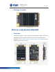
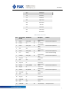
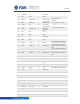
Table Of Contents
- 1 Overview
- 2 WisLink LoRa Module RAK2287
- 3 Schematics Reference
- 4 Contact Information
- 5 Warning
- 6 Revision History
- 7 Document Summary
9
RAK2287
9
2.9 RESET
RAK2287 card includes the RESET active-high input signal to reset the radio
operations as specified by the SX1302 Specification.
2.10
Antenna RF Interface
The modules have two RF interfaces over standard UFL connector (Hirose U. FL-R-
SMT) with the characteristic impedance of 50Ω. Port (J1) is the LoRa antenna interface
and Port (J2) is the GPS antenna interface.
2.11
Electrical Characteristics
Stressing the device above one or more of the ratings listed in the Absolute Maximum
Rating section may cause permanent damage. These are stress ratings only.
Operating the module at these or at any conditions other than those specified in the
Operating Conditions sections of the specification should be avoided. Exposure to
Absolute Maximum Rating conditions for extended periods may affect device reliability.
The operating condition range define those limit within which the functionality of the
device is guaranteed. Where application information is given, it is advisory only and
does not form part of the specification.
2.11.1
Absolute Maximum Rating
Limiting values given below are in accordance with the Absolute Maximum
Rating System (IEC 134).
Symbol Description Condition Min. Max.
3.3Vaux
Module supply
voltage
Input DC voltage at
3.3Vaux pins
–0.3V 3.6V
USB
USB D+/D- pins
Input DC voltage at USB
interface pins
3.6V
RESET
SX1302 reset
input
Input DC voltage at
RESET input pin
–0.3V 3.6V
SPI
SPI interface
Input DC voltage at SPI
interface pin
–0.3V 3.6V
PPS
GPS pps output
Output DC voltage at
PPS output pin
–0.3V 3.6V
Rho_ANT
Antenna
ruggedness
Output RF load mismatch
ruggedness at ANT1
10:1VSW
R