
User's Manual
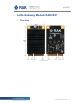
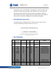
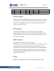
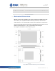
Table Of Contents

8
RAK2247
8
RAK2247 User Manual V1.0
2.8 RESET
RAK2247 card includes the RESET active-high input signal to reset the radio
operations as specified by the SX1301 Specification.
2.9 Antenna RF Interface
The modules have one RF interfaces over a standard UFL connectors (Hirose U.
FL-R-SMT) with a characteristic impedance of 50OHM. The RF port (J1) supports
both Tx and Rx, providing the antenna interface.
2.10 Electrical Characteristics
Stressing the device above one or more of the ratings listed in the Absolute
Maximum Rating section may cause permanent damage. These are stress ratings
only. Operating the module at these or at any conditions other than those specified
in the Operating Conditions sections of the specification should be avoided.
Exposure to Absolute Maximum Rating conditions for extended periods may affect
device reliability. The operating condition range define those limit within which the
functionality of the device is guaranteed.
Where application information is given, it is advisory only and does not form part of
the specification.
2.10.1 Absolute Maximum Rating
Limiting values given below are in accordance with the Absolute Maximum Rating
System (IEC 134).
Symbol Description Condition Min. Max.
3.3Vaux Module supply voltage Input DC voltage at 3.3Vaux pins –0.3V 3.6V
USB USB D+/D- pins Input DC voltage at USB interface pins 3.6V
SPDT_SEL Port select Input DC voltage at SPDT_SEL input pins –0.3V 3.6V
RESET RAK2247 reset input Input DC voltage at RESET input pin –0.3V 3.6V
SPI SPI interface Input DC voltage at SPI interface pin –0.3V 3.6V
GPS_PPS GPS 1 pps input Input DC voltage at GPS_PPS input pin –0.3V 3.6V
Rho_ANT Antenna ruggedness Output RF load mismatch ruggedness at ANT1 10:1 VSWR
Tstg Storage Temperature –40°C 85°C
Table 3 | Absolute maximum ratings