
User's Manual


Information in this document is subject to change without prior notice. Page
3 of 13
3.2 Block Diagram
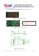
RF
Receiver
RF
Transmitter
Baseband
MAC/
Packet
Buffer/
Encrption
Engine
DATA-
USB
Interface
VCC (5V)
DATA+
GND
RT5372
3.3V/1.5V
5V/3.3V
I-PEX
Receptacle
USB
Connector
USB WiFi adapter
TX CONTROL
EXTERNAL LED
TX/RX
Front End
WPS CONTROL
I-PEX
Receptacle
External antenna
External antenna
2.412~2.462GHz
Figure 1: System Block Diagram of 7 pin GWF-1M01 5.0V WLAN Module
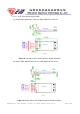
RF
Receiver
RF
Transmitter
Baseband
MAC/
Packet
Buffer/
Encrption
Engine
DATA-
USB
Interface
VCC (5V)
DATA+
GND
RT5372
3.3V/1.5V
I-PEX
Receptacle
USB
Connector
USB WiFi adapter
TX CONTROL
EXTERNAL LED
TX/RX
Front End
WPS CONTROL
I-PEX
Receptacle
External antenna
External antenna
Figure 2: System Block Diagram of 7 pin GWF-1M04 3.3V WLAN Module
2.412~2.462GHz
2.412~2.462GHz
2.412~2.462GHz