
User's Manual

WM620 Hardware User Guide V1.1
All rights reserved by Shenzhen Neoway Technology Co., Ltd. Page 9
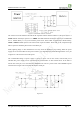
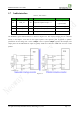
2.4 SIM Card
PIN
Signal name
I/O
Function description
Note
13
V_SIM
PWR
SIM ard power output
1.8/3.0V
14
SIM_CLK
DO
SIM card clock output
1.8/3.0V
15
SIM_RST
DO
SIM card reset output
1.8/3.0V
16
SIM_DATA
I/O
SIM card data input/output
1.8/3.0V
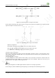
WM620 module supports 3V & 1.8V SIM cards. The SIM_DATA pin needs an externally 10K pull-up
resistor connected to V_SIM.The SIM_CLK is the clock signal, normally 3.25MHz. Bifurcation is not
recommended at the PCB trace of SIM_CLK.
Include SIM_DATA and SIM_CLK, the traces should be as short as possible and surrounded by the ground
copper to reduce the RF interference. The total distributed capacitance, include the junction capacitance of the
ESD diode or other device, can’t be higher than 120pF.
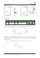
Figure 2-9a, SIM card and ESD devices
Figure 2-9b, the recommended ESD diode array
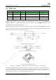
Figure 2-9c, a sample of SIM card socket
PIN1, VCC PIN2, RST PIN3, CLK PIN4, GND PIN5, VPP PIN6, DATA
The SIM card application circuit is shown in Figure 2-9. In automotive electronics or other applications with
strong ESD, ESD diodes or ESD varistors are strongly recommended, such as T1 to T4. T1 to T4 should be
place closed to SIM card. In some clear applications, SIM card is installed in closed box without human touch,
22~33pF MLCC capacitors can replace the ESD diodes for cost down.