
User's Manual

M590 GPRS Module Hardware User Guide
Copyright © Neoway Technology Co., Ltd
20
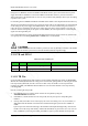
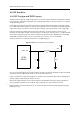
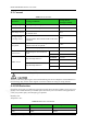
Figure 3-20 RF layout reference
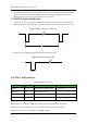
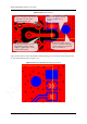
If you use RF feeder to connect the module and the antenna (pin 21 is not used), remove the pad of the
21
st
pin and its adjuncts. Refer to Figure 3-21.
Figure 3-21 Reference RF design when pin 21 is not used
Ensure complete ground at both
sides of the 20
th
pin. Avoid
ground at only one side.
The RF route should be as short
and smooth as possible and at a
width of 1 mm; the RF is 1 mm
away from the ground.
Separate the copper-removing
area from the RF route by
ground.
Remove the copper from the
top layer of the RF testing point
(2mm in diameter). Dig ground
holes around this are.